CNC Machined Heavy-Duty Support Block

CNC Machined Heavy-Duty Support Block with raised contact pads, mounting holes, reinforced edges and beveled positioning surfaces for equipment support, spacing, impact protection and load distribution. Available in UHMWPE, HDPE, PA nylon and other engineering plastics, with dimensions and structures manufactured according to drawings or physical samples.

category Brand:
Share :

Description

Product Description

CNC Machined Heavy-Duty Support Block for Equipment Support

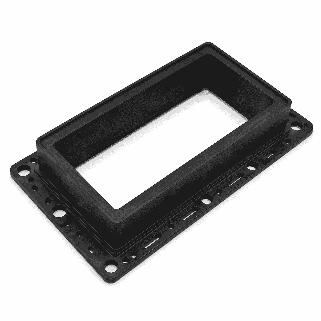
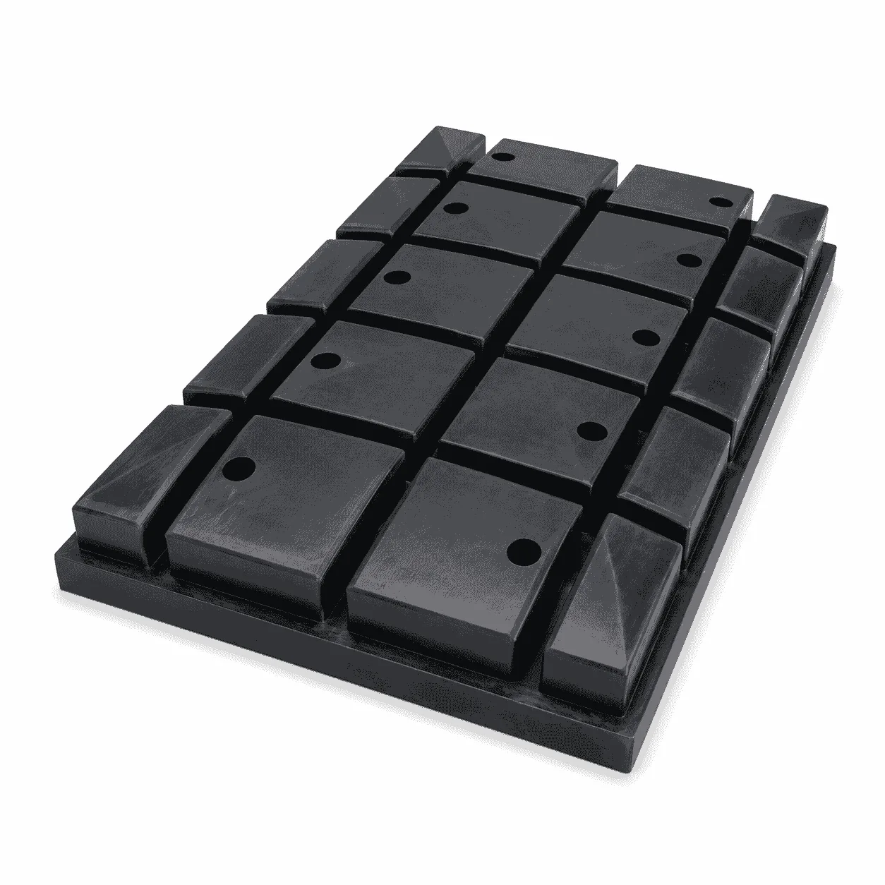
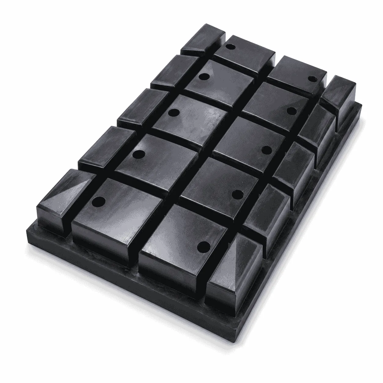
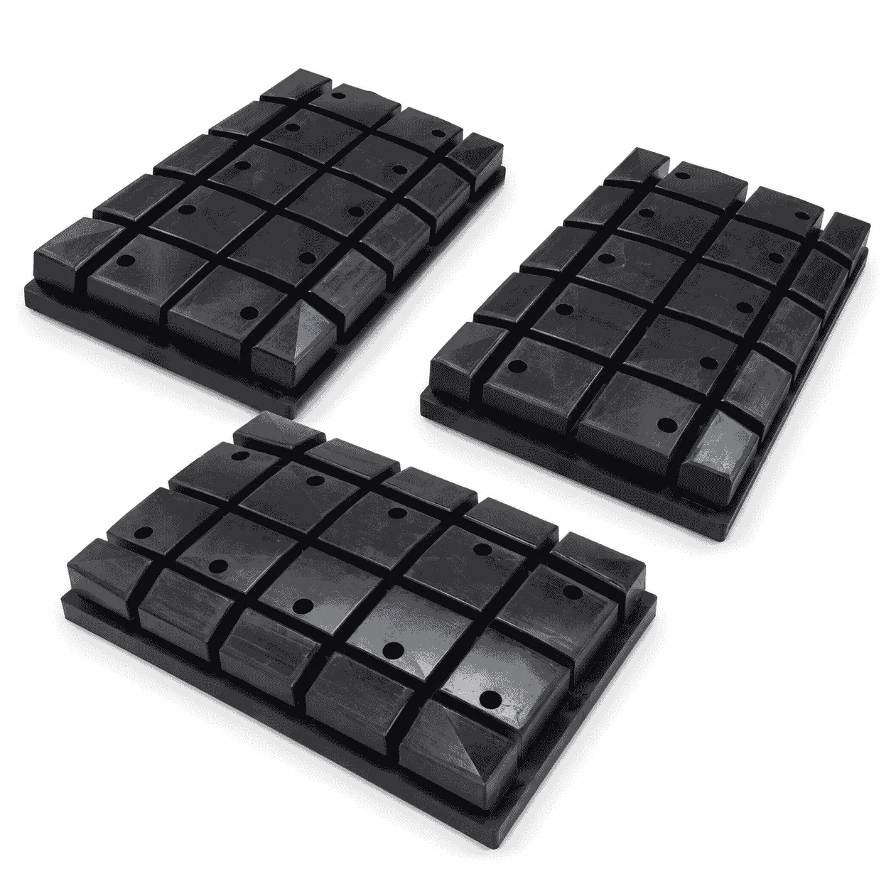
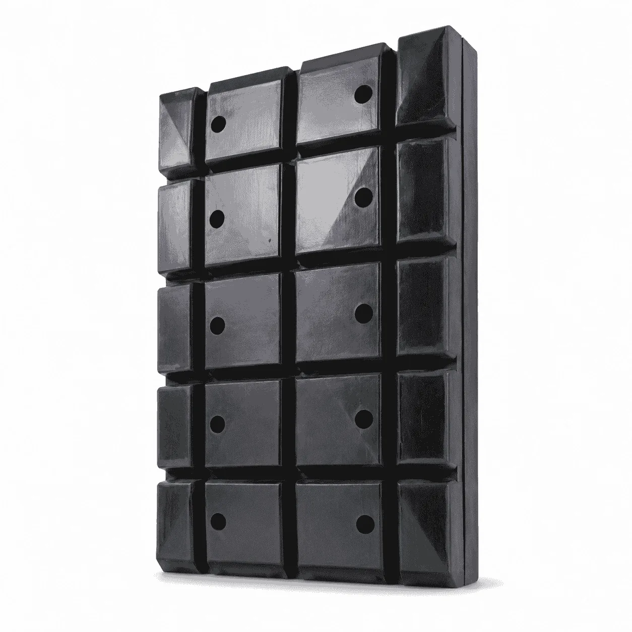
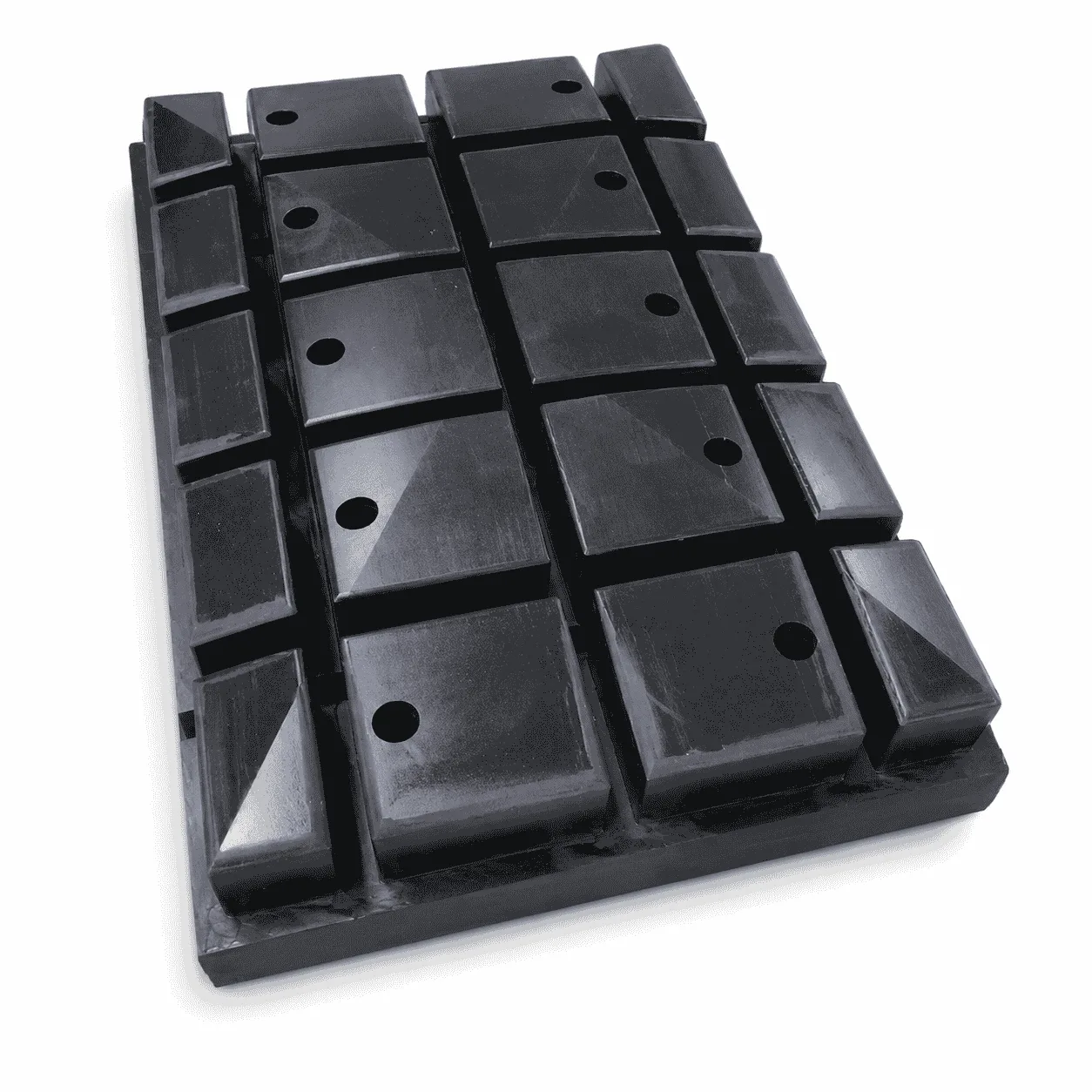
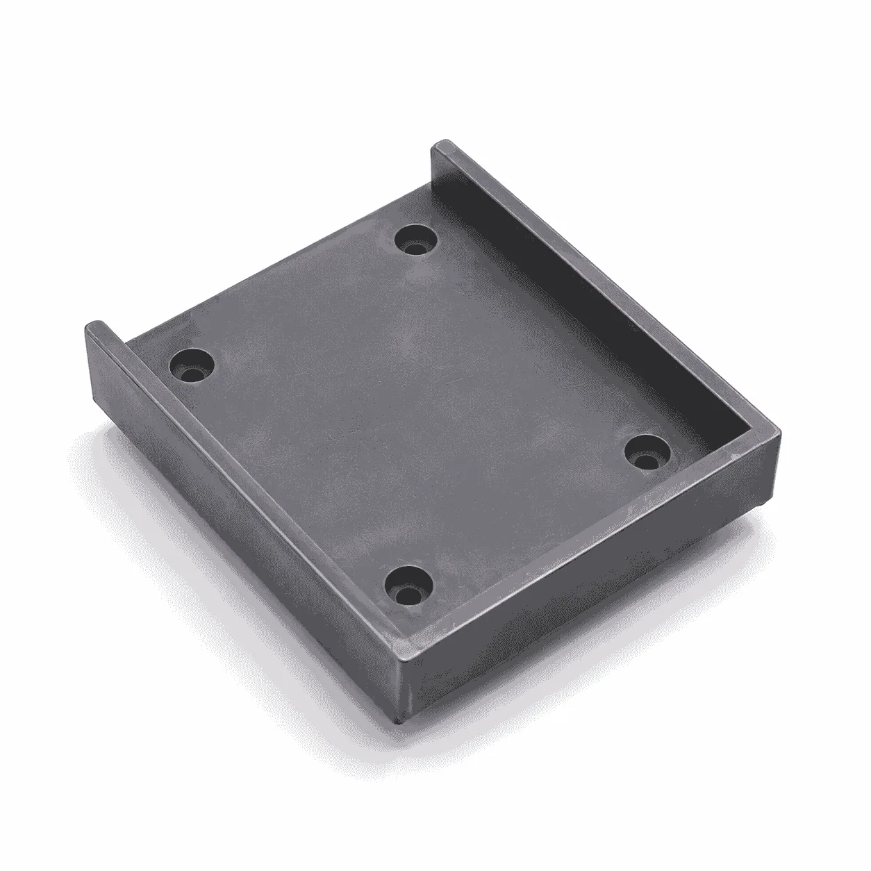
The CNC Machined Heavy-Duty Support Block is a rigid engineering plastic component designed for supporting, positioning, spacing, isolating or protecting heavy machinery and industrial assemblies. The product shown in the image features a black rectangular body, multiple raised contact sections, machined mounting holes, reinforced side structures and beveled edge areas.

The divided upper contact surfaces can provide several defined supporting or positioning points instead of relying on one completely flat surface. The mounting holes may be used for bolting, positioning, lifting, connecting or securing the block to a machine frame, base plate or corresponding assembly.

The raised edge sections and recessed channels may help locate the mating equipment, separate different contact areas or reduce unwanted movement. Their exact function depends on the original equipment design and must be confirmed from the approved drawing, physical sample or installation assembly.

The image does not confirm a universal material grade, standard dimension, certified working load or specific equipment model. Final material, structure, tolerances and allowable load must be determined according to the actual application.

How the CNC Machined Heavy-Duty Support Block Works

The support block is normally positioned between a machine, structural component, vehicle assembly, fixture or heavy object and its supporting base. It creates a defined contact interface that can distribute pressure, control installation height and separate the supported component from the floor or metal frame.

Depending on the installation, the block may carry a mainly compressive load, provide lateral positioning or receive intermittent impact. It may also be used as a replaceable wear or protective component where direct contact could otherwise damage a machine base, mounting surface or supporting structure.

The mounting holes can help retain the block in a fixed position. Where the holes are used with bolts, the bolt diameter, washer size, tightening torque and remaining material around the hole should be reviewed together to avoid localized stress or cracking.

The raised contact sections should correspond to the load-bearing points of the mating component. Uneven contact, a tilted supporting surface or concentrated loading on one corner may create excessive local pressure even when the total equipment weight appears acceptable.

Material Options for Heavy-Duty Support Blocks

This product can be manufactured from UHMWPE sheet, HDPE, PA nylon or other suitable engineering plastics. The material should be selected according to load, impact, temperature, moisture, chemical exposure, dimensional stability and required service life.

UHMWPE Material

Ultra-high-molecular-weight polyethylene may be considered where impact resistance, wear resistance, low moisture absorption and a relatively low-friction contact surface are important. General material information is available from the Wikipedia explanation of UHMWPE.

UHMWPE is frequently used for wear pads, guide blocks, liners, support components and impact-resistant industrial parts. It should not automatically be assigned a load rating without confirming the material grade, dimensions and testing conditions.

HDPE Material

HDPE may be evaluated for structural support blocks requiring good moisture resistance, chemical resistance and easier material processing. General information is available from the Wikipedia explanation of HDPE.

The practical differences between the two polyethylene materials are explained in our UHMWPE vs HDPE comparison. UHMWPE is generally considered where wear, impact and sliding performance are priorities, while HDPE may be suitable for general structural and fabricated components.

PA Nylon Material

PA6, MC nylon or PA66 may be considered where greater rigidity, mechanical strength or precision machining is required. Nylon can absorb moisture, so dimensional changes and fitting clearances should be evaluated for humid or water-contact environments.

The black color shown in the image does not identify the material by itself. UHMWPE, HDPE, nylon and other engineering plastics can all be supplied in black formulations. Raw-material specifications should be used to confirm the final grade.

7 Proven Benefits of the CNC Machined Heavy-Duty Support Block

  • Load distribution: the machined contact surfaces can help spread equipment pressure across defined supporting areas.
  • Impact protection: suitable engineering plastics can absorb moderate impact and vibration in approved applications.
  • Equipment positioning: raised sections, edges, holes and recessed areas can help locate the corresponding component.
  • Surface isolation: the block separates metal equipment from floors, frames or other contact surfaces.
  • Corrosion-free body: engineering plastic does not rust like ordinary carbon steel support components.
  • Lower component weight: plastic support blocks are generally easier to handle than equivalent solid steel blocks.
  • Flexible machining: contact steps, mounting holes, grooves, bevels and external profiles can be produced according to drawings.

Raised Contact and Reinforced Structure

The pictured block contains multiple rectangular raised sections separated by recessed channels. These sections may be used as support pads, positioning areas or contact points for the mating equipment.

The channels may provide clearance for corresponding structures, prevent interference, separate load areas or allow dirt and small debris to move away from the primary contact surfaces. Their function should be confirmed from the assembly drawing rather than assumed only from the product appearance.

The raised blocks should have sufficient wall thickness and smooth transitions at their roots. Sharp internal corners may create stress concentration when the component receives repeated compression or impact.

The side blocks and beveled edges may assist with positioning, installation clearance or gradual contact with another machine component. The bevel angle, height and orientation should follow the equipment structure.

Mounting-Hole Options

The CNC Machined Heavy-Duty Support Block can be produced with different mounting and positioning structures:

  • Straight through holes
  • Counterbored mounting holes
  • Countersunk holes
  • Threaded holes
  • Elongated adjustment slots
  • Metal threaded inserts
  • Locating-pin holes
  • Lifting or handling holes
  • Recessed bolt-head positions
  • Retaining and alignment grooves

Where a metal insert is required, the insert dimensions and installation method should be selected according to tightening torque and maintenance frequency. A bolt should not be excessively tightened directly against an unsupported plastic surface.

Typical Applications

The product can be used in industrial assemblies requiring support, cushioning, positioning, spacing or protection between heavy components.

  • Heavy machinery base supports
  • Equipment installation and alignment blocks
  • Mining and material-handling machinery
  • Construction machinery support components
  • Vehicle and mobile-equipment maintenance
  • Hydraulic equipment positioning blocks
  • Industrial press and fixture supports
  • Production-line equipment foundations
  • Warehouse and transfer equipment
  • Machine-frame isolation pads
  • Replaceable impact and wear blocks
  • Temporary equipment support arrangements

Plastic blocks may also be used in cribbing or temporary stabilization systems. Cribbing generally refers to blocks arranged to support or stabilize heavy objects. A general explanation is available from the Wikipedia overview of box cribbing.

However, the pictured product should not automatically be described as certified cribbing equipment unless its material, stacking structure and load rating have been specifically designed and tested for that purpose.

Critical Dimensions and Design Requirements

The overall length, width and thickness determine the available supporting area and installation height. The dimensions of each raised contact section determine how the load is transferred into the main body.

Important dimensions may include:

  • Overall length and width
  • Total block thickness
  • Raised contact height
  • Width and length of each contact pad
  • Recessed channel width and depth
  • Mounting-hole diameter
  • Mounting-hole spacing
  • Edge-block dimensions
  • Bevel angle and bevel height
  • Bottom-surface flatness
  • Contact-surface parallelism
  • Minimum remaining wall thickness

The supporting base should be sufficiently flat, rigid and stable. A heavy-duty block placed on loose, sloped or uneven ground may not distribute the load as intended.

Where several blocks are used together, their finished height should be consistent. Height variation may cause one block to receive a disproportionate share of the equipment load.

CNC Machining Capabilities

Through our engineering plastic machining service, the CNC Machined Heavy-Duty Support Block can be produced by cutting, milling, drilling, boring, slotting, profiling, chamfering and deburring.

Available processing details include:

  • Large rectangular block machining
  • Raised and recessed contact surfaces
  • Stepped supporting structures
  • Mounting and positioning holes
  • Counterbores and countersinks
  • External bevels and angled surfaces
  • Side locating blocks
  • Internal and external grooves
  • Rounded corners and finished edges
  • Drawing numbers and batch identification

The component can be manufactured according to technical drawings, three-dimensional models, physical samples or verified installation dimensions. Material and machining routes should be confirmed before batch production.

Production and Quality Inspection

First-piece inspection should be completed before continuous batch machining. Important inspection items include the overall dimensions, contact-pad height, hole diameter, hole spacing, channel depth, bevel angle and bottom-surface flatness.

The product should be checked for cracks, voids, excessive deformation, incomplete machining and sharp burrs. Mounting holes and recessed areas should be cleaned before packaging.

During batch processing, dimensional sampling helps control variation caused by cutting-tool wear, material temperature and internal stress. Products with different specifications should be separated and identified to prevent mixing during installation.

Load and Safety Considerations

The finished support block should not be assigned a working-load limit solely from its outside dimensions. Allowable load depends on the material grade, contact area, block thickness, load duration, temperature, impact, support conditions and safety factor.

Engineering plastics can gradually deform under prolonged compressive loading. This time-dependent deformation should be considered where the block remains continuously loaded for long periods.

Applications involving lifting, personnel access, vehicle stabilization or work beneath suspended equipment require verified engineering calculations, load testing and approved operating procedures.

A damaged block showing cracking, permanent deformation, enlarged mounting holes or severe surface damage should be removed from service and evaluated before reuse.

Information Required Before Production

To manufacture the CNC Machined Heavy-Duty Support Block accurately, please provide the overall length, width, thickness, contact-pad dimensions, channel dimensions, mounting-hole positions, bevel structure, material grade, tolerances and required quantity.

Please also provide the equipment model, installation position, load direction, maximum static load, impact conditions, supporting-surface condition, operating temperature, chemical contact and required service life where available.

The image is provided as an appearance and structural reference only. It does not confirm a universal size, material grade, certified load capacity or equipment compatibility. Final specifications and application suitability must follow the approved drawing, material data, engineering review and actual operating requirements.

Quality Control

Quality Control and Delivery Standards

Drawing & Material Check

Check drawings for full specifications and confirm materials according to service conditions to prevent product defects.

Machining Quality Control

Inspect all key processing steps and fully verify dimensions, holes, grooves and fitting surfaces.

Finishing & Batch Control

Deburr, chamfer and clean products for easy installation. Ensure uniform quality among batch products.

Packaging & Delivery

Choose appropriate packaging solutions based on product features to protect goods from collision, deformation and mixing during transit.

Processing Quality Control of Engineering Plastics Parts

Unlike metal parts, engineering plastic components still require strict control over dimensions, holes, edges, surface, materials and assembly performance for equipment use.

application

Applications for Engineering Plastic Parts

Engineering plastic parts suit friction, guide, support, buffer, anti-corrosion and insulation areas. We supply UHMWPE, POM, PA, PP/PE components for conveyor, food, mining, machinery, chemical and cable systems, with custom OEM service available.

Our Blog

Latest News & Knowledge

Stay updated with our latest industry insights, company updates and featured articles.

We Love to Hear From You

Need UHMWPE sheets & custom plastic machined/OEM parts?Send specs & material needs, free quote within 24h.