

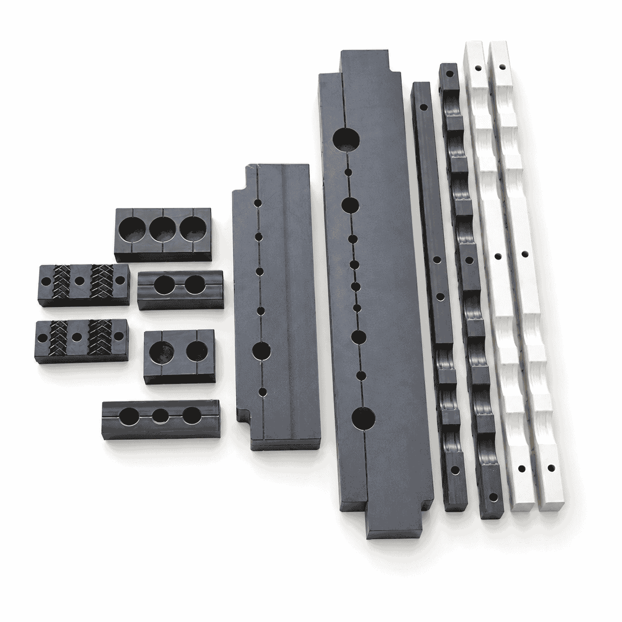
CNC Machined Nylon Cable Conduit Clamp with a split structure and single or multiple cable grooves for cable support, separation, positioning and movement restriction. Available with different groove diameters, mounting holes, counterbores, textured surfaces and long-strip structures. PA6, MC nylon, PA66 and modified nylon options can be manufactured according to drawings or physical samples.
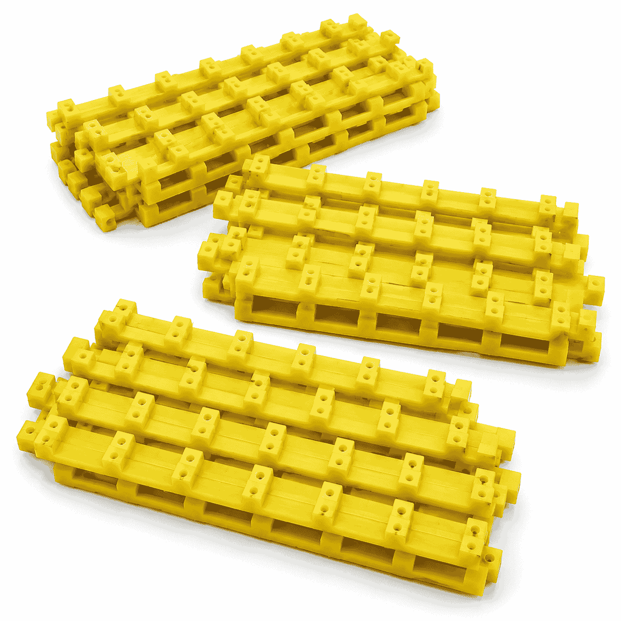
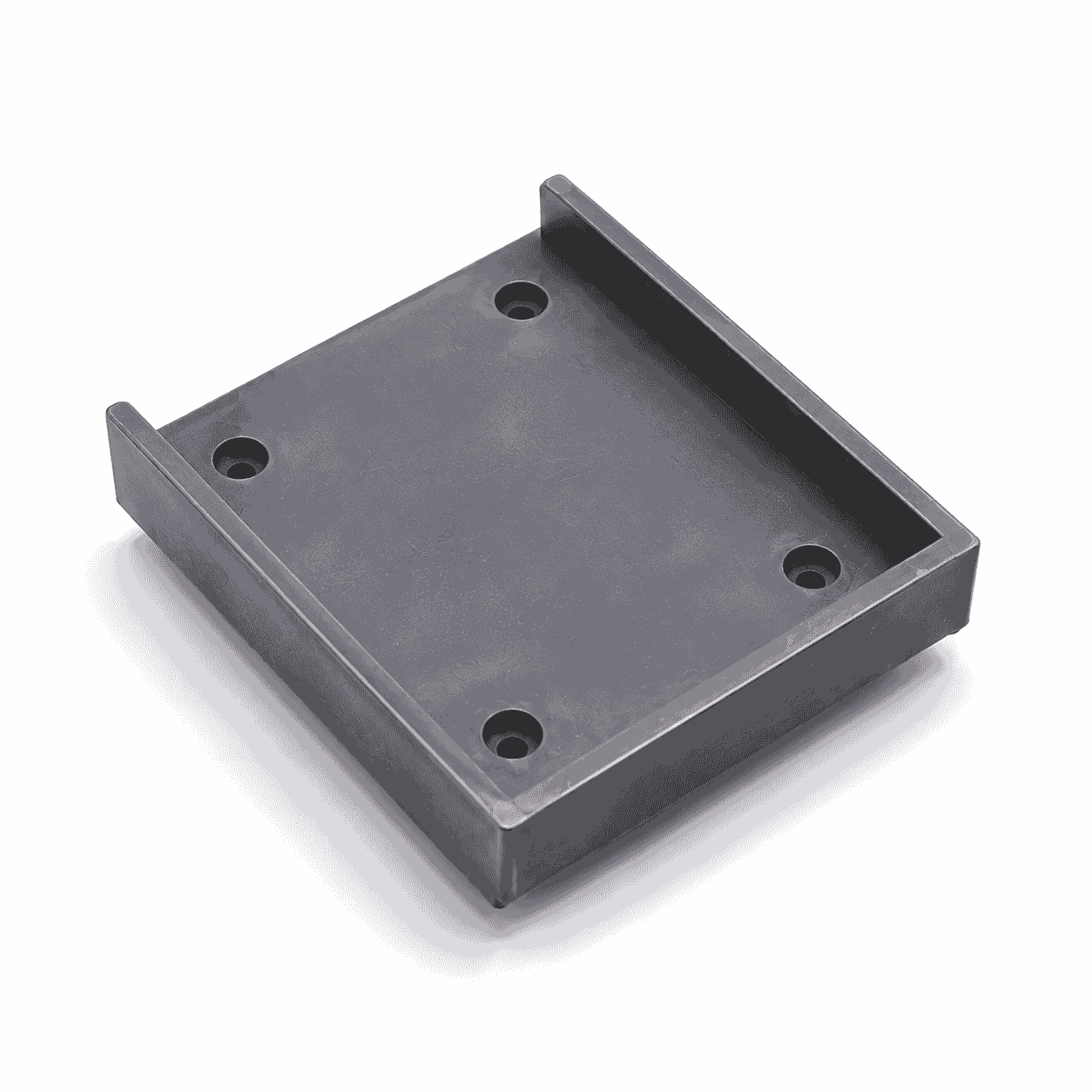
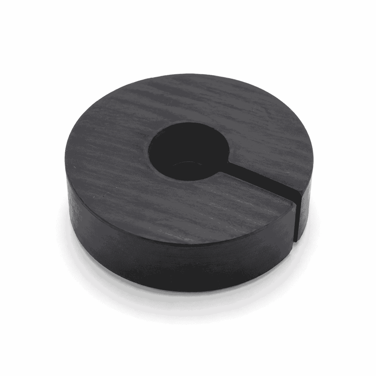
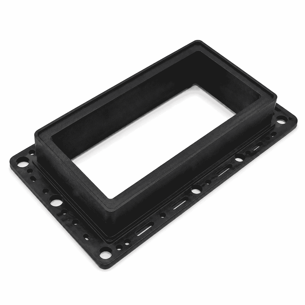
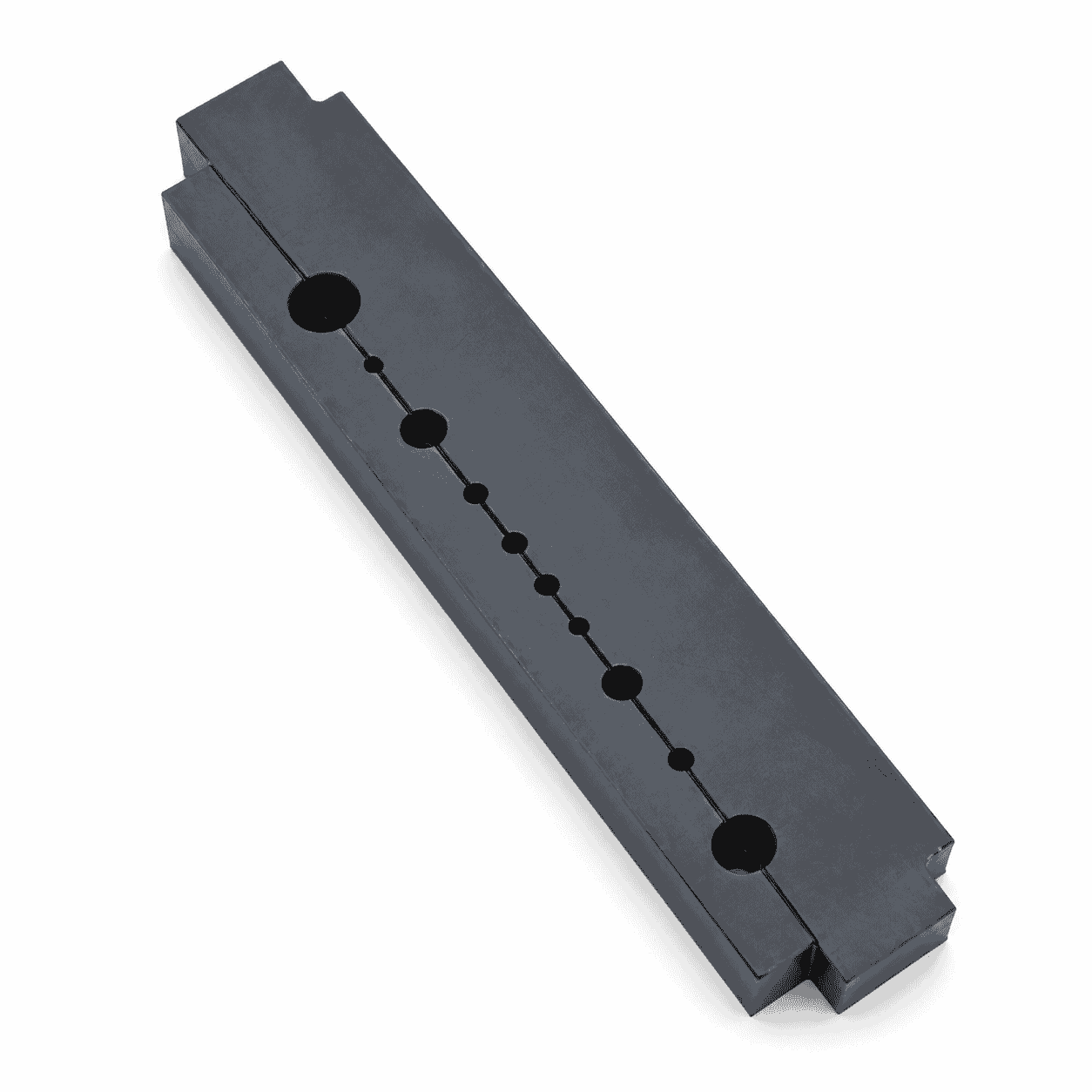
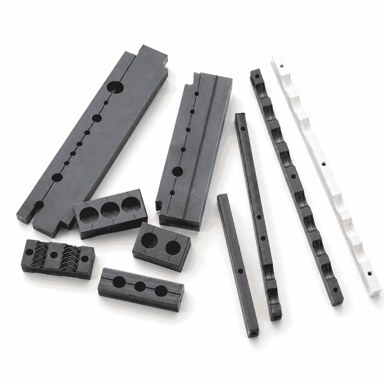
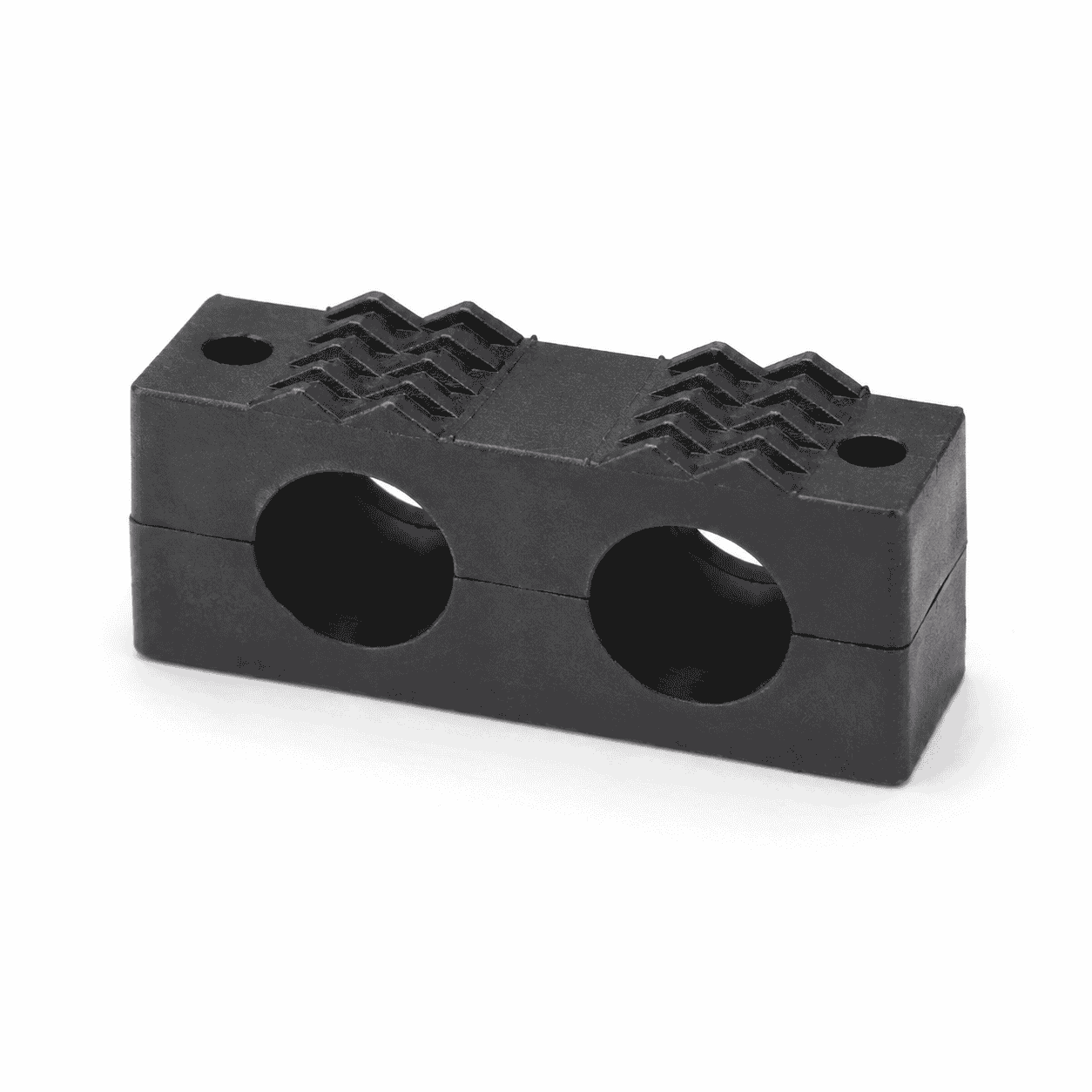
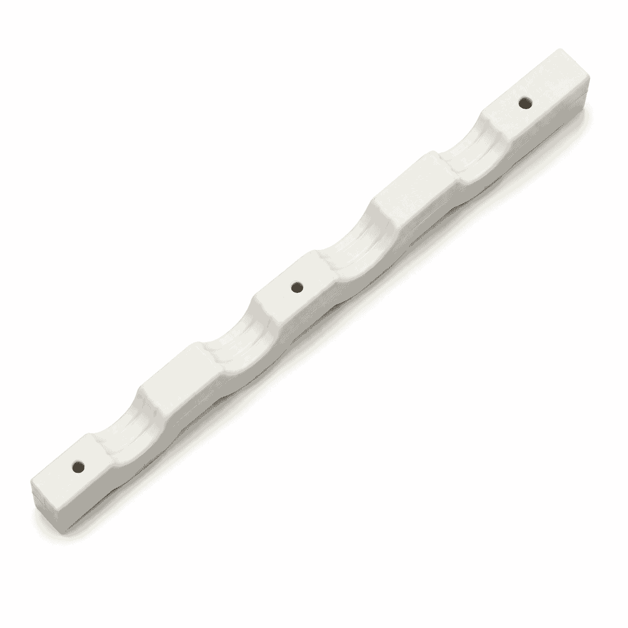
The CNC Machined Nylon Cable Conduit Clamp is a precision engineering plastic component designed to support, separate, position and retain electrical cables, protective conduits, hoses or other cylindrical lines in industrial equipment. The products shown in the image include natural-colored and dark-colored split clamp blocks with single, double and multiple semicircular cable grooves.
The pictured components are available in short block, long strip and multi-channel structures. Several products include mounting holes, counterbores, side holes, locating steps and textured contact surfaces. Depending on the equipment design, the clamp may be fixed to a machine frame, cable tray, mounting plate, support bracket or other structural component.
The split structure allows the corresponding cable or conduit to be placed between two matching clamp halves. After the fasteners are installed, the curved internal grooves help maintain cable spacing and restrict unwanted radial movement.
The image does not confirm one universal cable diameter, nylon grade, clamping force, voltage class or equipment model. Final dimensions, materials, fastening structures and installation clearances must follow the approved drawing, physical sample or verified equipment requirements.
The clamp normally consists of an upper section and a lower section, each containing one or more semicircular grooves. When the two sections are assembled, the corresponding grooves form complete circular or partially enclosed cable channels.
The assembled clamp helps hold cables or conduits in a defined position while maintaining the required spacing between adjacent lines. It may also restrict movement caused by machine vibration, cable weight, equipment travel or repeated starting and stopping.
Depending on its installation position, the component may provide several functions:
The groove diameter should correspond to the outside diameter of the cable, hose or conduit. A groove that is too small may create excessive compression or damage the outer covering. A groove that is too large may allow vibration, impact and unstable positioning.
This component can be produced from Polyamide PA Nylon Rod, nylon sheet or a suitable molded nylon blank. Possible options include PA6 nylon, cast MC nylon, PA66 nylon, oil-filled nylon, MoS₂-filled nylon and other modified polyamide grades.
Nylon is a family of synthetic polymers characterized by repeating amide linkages. Different formulations can provide different combinations of mechanical strength, toughness, wear resistance, rigidity and machinability. General material information is available from the Wikipedia explanation of nylon.
PA6 may be considered for general-purpose cable clamp blocks requiring balanced toughness and machining performance. Cast MC nylon may be suitable for thicker, larger or long-strip clamp structures. PA66 may be evaluated where greater rigidity and mechanical strength are required.
Modified nylon formulations may be considered where the clamp is exposed to repeated vibration, sliding contact or more demanding mechanical conditions. The final material should be selected according to cable weight, operating temperature, humidity, chemical exposure, impact and expected service life.
The natural, black and dark-grey colors shown in the image do not independently identify the nylon grade. Similar-looking parts may use different materials, pigments or additives. Raw-material specifications should therefore be confirmed through drawings, purchase requirements or material certificates.
A single-groove clamp supports one cable, conduit or hose. It can be used where each line requires an individual mounting position or where the cable route includes changes in direction.
A multi-groove clamp supports several parallel cables within one component. This arrangement can maintain consistent spacing, simplify equipment assembly and reduce the number of separate mounting blocks required.
The image shows several structural options:
Different groove diameters may be combined in one clamp when the equipment contains power cables, control cables, protective conduits or hoses of several sizes.
Some dark-colored components in the image include textured or patterned groove surfaces. These structures may increase local contact or reduce movement in selected installations. However, they should not be used where the pattern could damage a soft cable jacket.
Smooth grooves are generally suitable where surface protection and easy cable installation are priorities. Rounded groove edges can reduce local pressure on cable insulation and protective conduit surfaces.
The groove surface should be free from burrs, sharp machining marks and debris. A suitable edge radius or chamfer may be added according to the cable covering and assembly method.
The clamp blocks shown in the image include several through holes and recessed mounting features. These structures allow the two halves to be connected or secured to the supporting equipment.
Available mounting options include:
Fasteners should be tightened evenly. Excessive tightening may deform the cable covering, reduce the groove diameter or create stress around the mounting holes. Insufficient tightening may allow the clamp halves or cables to move during equipment operation.
Metal sleeves or inserts can be considered where bolts are repeatedly removed or where higher fastening force is required. The remaining nylon wall thickness around each hole must be sufficient for the intended assembly load.
The CNC Machined Nylon Cable Conduit Clamp can be used in machinery and installations requiring cable support, separation and routing.
Electrical conduit is a tube used to protect and route electrical wiring, and it may be produced from metal, plastic or other materials. General information is available from the Wikipedia explanation of electrical conduit.
Cable tray systems support insulated electrical cables and may use specialized clamps, supports and accessories to maintain cable routes and spacing. More general information is available from the Wikipedia explanation of cable trays.
Additional engineering plastic applications are available on our Industrial Machinery application page.
A cable conduit clamp is primarily used to support, position and restrict the movement of a cable or conduit along its route. It does not automatically provide environmental sealing or strain relief at the cable entry point of an enclosure.
A cable gland is a separate cable-entry device designed to attach and secure the end of a cable to equipment and may also provide sealing or strain relief. The pictured nylon clamp blocks should therefore not be described as cable glands unless their structure has been specifically designed and tested for that function.
The cable or conduit outside diameter should be measured before the groove diameter is confirmed. Cable coverings may vary because of manufacturing tolerance, armour, protective layers or operating temperature.
The finished groove may use a small clearance or controlled contact according to the required holding function. It should not apply uncontrolled crushing pressure to electrical insulation, optical fibre cables, flexible hoses or thin-wall conduits.
Nylon can absorb moisture and may undergo dimensional changes in humid or water-contact environments. Temperature changes may also affect the groove and mounting-hole dimensions. These factors should be considered for close-fitting clamps.
For moving cables, sufficient bending radius and movement allowance must be maintained outside the clamped area. The clamp should not force a cable into a bend tighter than the cable manufacturer’s permitted radius.
Through our CNC Plastic Machining service, the CNC Machined Nylon Cable Conduit Clamp can be produced by cutting, milling, drilling, boring, slotting, tapping, contour machining, chamfering and deburring.
Available machining details include:
Products can be manufactured according to two-dimensional drawings, three-dimensional models, physical samples or verified equipment installation dimensions.
For batch manufacturing, first-piece inspection should be completed before continuous processing. Important inspection dimensions include groove diameter, channel spacing, overall length, width, thickness, mounting-hole diameter and hole-center distance.
Corresponding upper and lower clamp sections should be checked together. After assembly, the cable channels should remain aligned without excessive steps or offsets between the two halves.
The groove surfaces should be inspected for burrs, sharp edges, cracks and excessive tool marks. Mounting holes and recessed areas should be cleaned before packaging.
During batch processing, dimensional sampling helps control variation caused by tool wear, raw-material temperature and internal material stress. Products with different cable diameters or drawing numbers should be separated and identified.
The cable, conduit and clamp grooves should be clean before installation. Metal chips, sand or hard particles trapped inside the groove may damage the cable covering.
Fasteners should be tightened gradually and evenly across the clamp. Where several bolts are used, alternating tightening can help maintain consistent pressure across the cable channels.
The clamp should be inspected periodically for looseness, cracking, deformation, enlarged mounting holes and cable movement. Cable coverings should also be checked for indentation, abrasion or other contact damage.
This product is a cable or conduit support and positioning component. It should not automatically be described as a watertight fitting, firestop, explosion-proof cable entry, electrical grounding component or certified strain-relief device.
Applications involving high voltage, fire resistance, explosion protection, personnel safety or regulatory certification require confirmation of the complete cable system, material grade, flame performance and installation standard.
To manufacture the CNC Machined Nylon Cable Conduit Clamp accurately, please provide the cable or conduit outside diameter, number of channels, groove spacing, block dimensions, mounting-hole positions, material grade, tolerance and required quantity.
Please also provide the equipment model, installation position, cable type, movement conditions, vibration, temperature, humidity, chemical exposure, fire-performance requirements and fastening method where available.
The image is provided as an appearance and structural reference only. It does not confirm a universal cable specification, nylon grade, clamping force, voltage class or equipment compatibility. Final specifications must follow the approved drawing, physical sample and actual operating requirements.
Check drawings for full specifications and confirm materials according to service conditions to prevent product defects.
Inspect all key processing steps and fully verify dimensions, holes, grooves and fitting surfaces.
Deburr, chamfer and clean products for easy installation. Ensure uniform quality among batch products.
Choose appropriate packaging solutions based on product features to protect goods from collision, deformation and mixing during transit.
Unlike metal parts, engineering plastic components still require strict control over dimensions, holes, edges, surface, materials and assembly performance for equipment use.
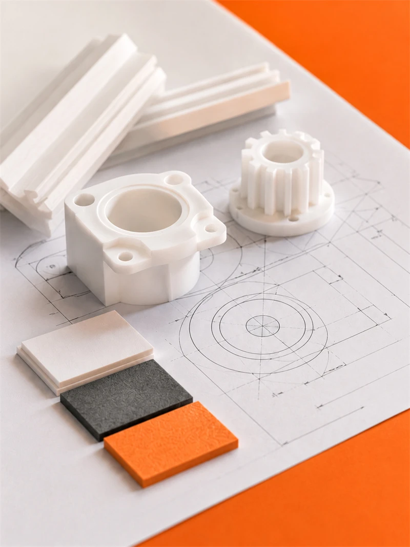
Engineering plastic parts suit friction, guide, support, buffer, anti-corrosion and insulation areas. We supply UHMWPE, POM, PA, PP/PE components for conveyor, food, mining, machinery, chemical and cable systems, with custom OEM service available.
Stay updated with our latest industry insights, company updates and featured articles.

Engineering plastics are increasingly used in industrial machinery, automated production lines, conveyor systems, packaging equipment, and food-processing machines. Materials such as nylon, UHMWPE, POM, and
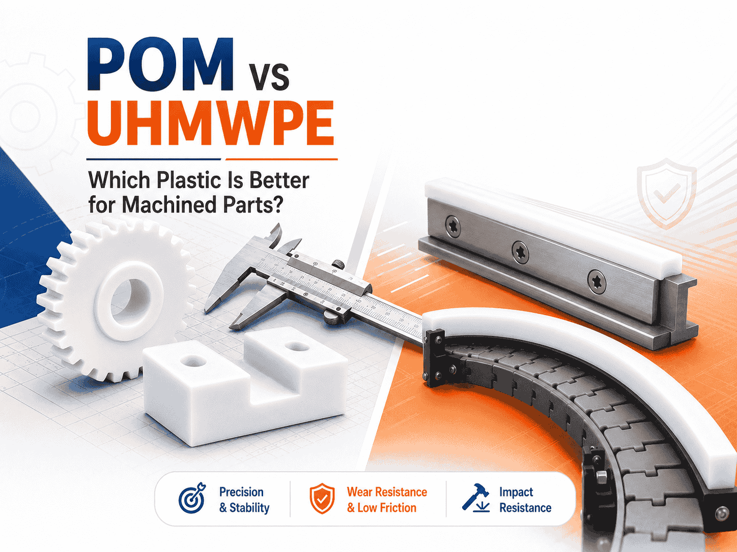
Both are lightweight, corrosion-resistant, wear-resistant, and suitable for CNC machining. However, they perform very differently
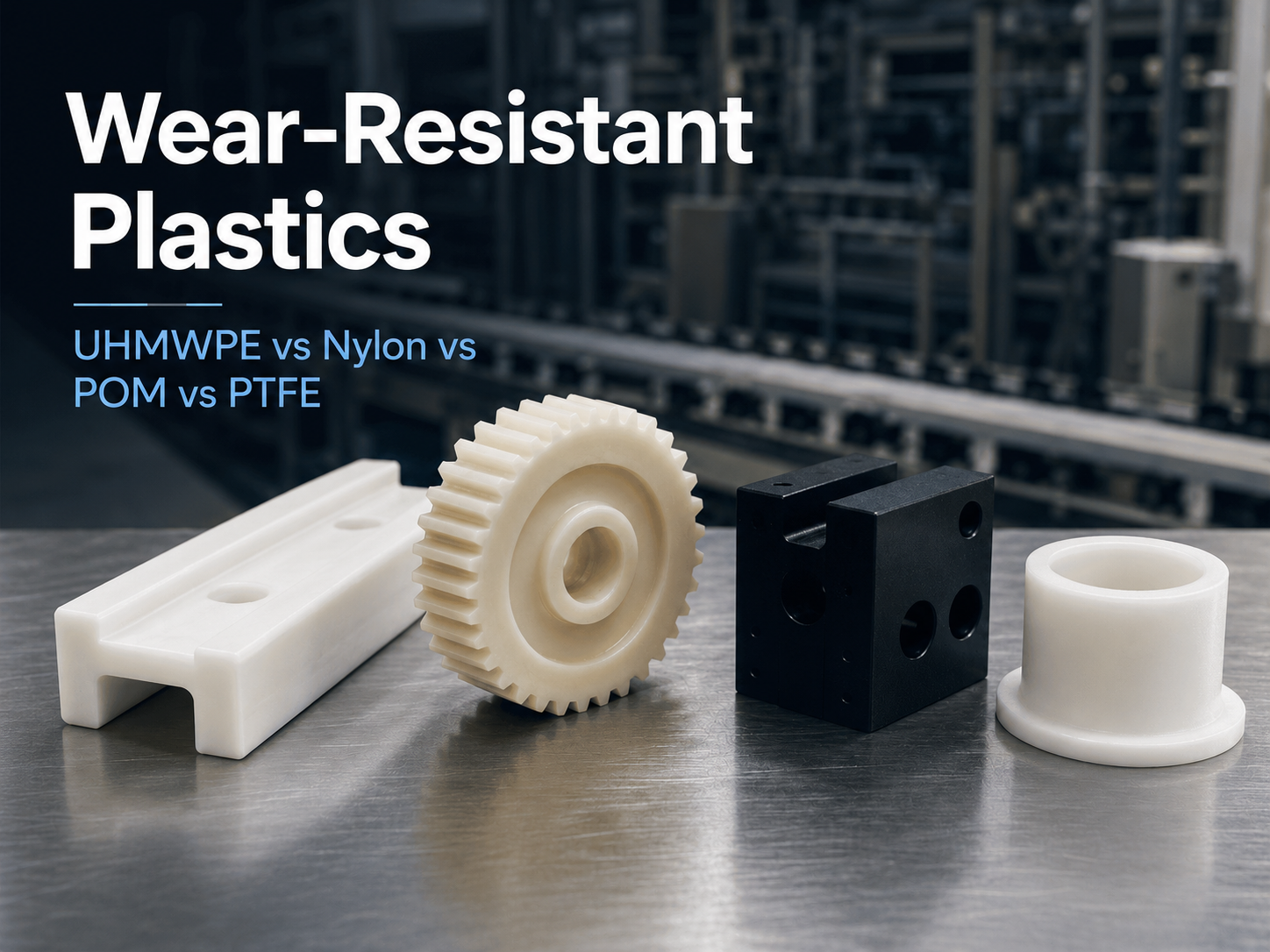
Wear is a common cause of failure in conveyor systems, packaging machinery, automated equipment, mining
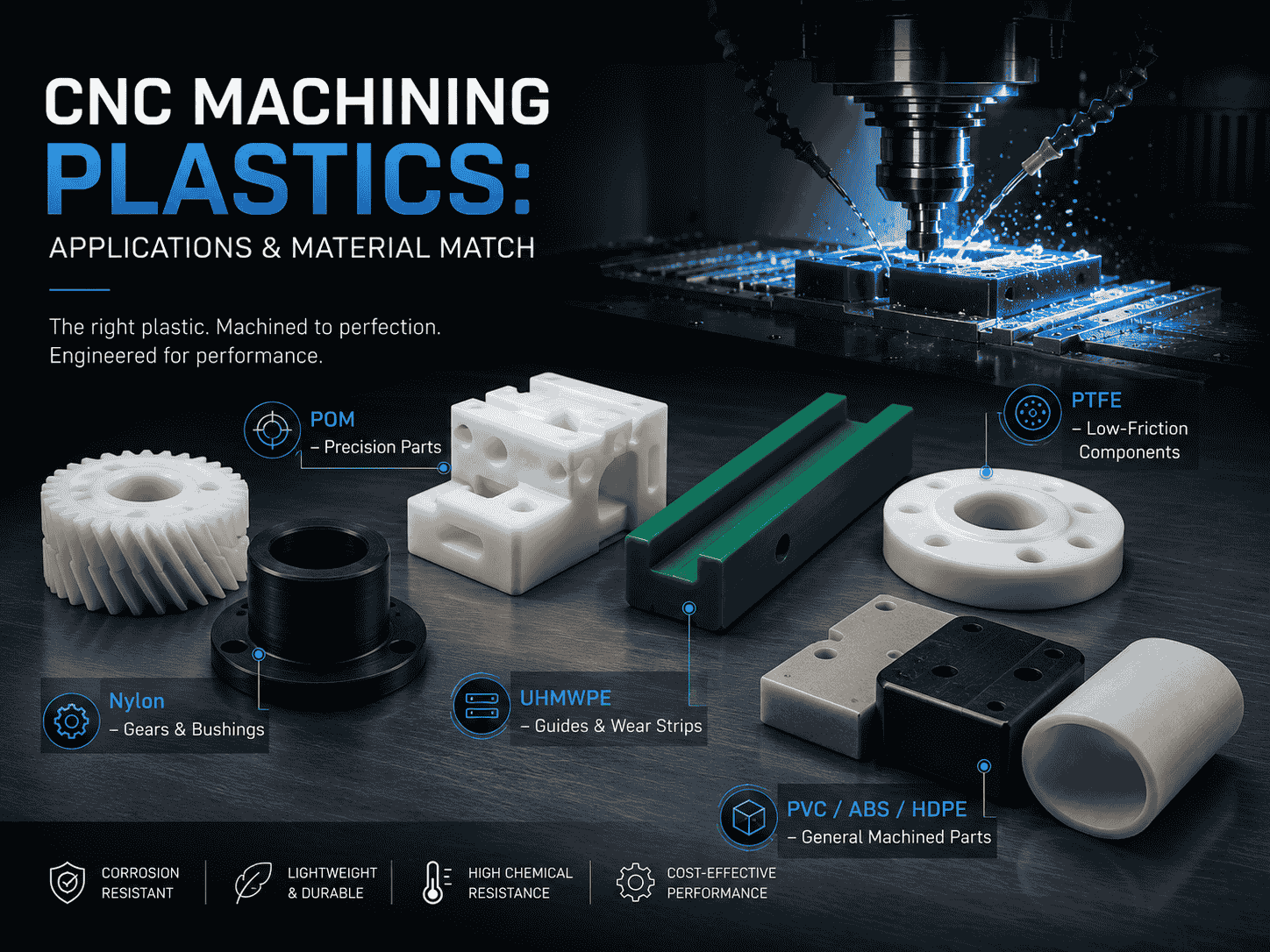
CNC machining is widely used to produce plastic prototypes, low-volume parts, replacement components, jigs, fixtures,
Both are lightweight, corrosion-resistant, wear-resistant, and suitable for CNC machining. However, they perform very differently
Wear is a common cause of failure in conveyor systems, packaging machinery, automated equipment, mining
CNC machining is widely used to produce plastic prototypes, low-volume parts, replacement components, jigs, fixtures,
Need UHMWPE sheets & custom plastic machined/OEM parts?Send specs & material needs, free quote within 24h.