CNC Machined Nylon Rope Guide Pulley for Tower Crane

CNC Machined Nylon Rope Guide Pulley with a deep circumferential groove, raised side flanges and precision center bore for guiding or redirecting wire ropes in tower cranes and approved lifting-equipment assemblies. Available in PA6, MC nylon, PA66 and modified nylon grades, with groove dimensions, bearing seats, bushings and fitting tolerances manufactured according to drawings or physical samples.

category Brand:
Share :

Description

Product Description

CNC Machined Nylon Rope Guide Pulley for Tower Cranes

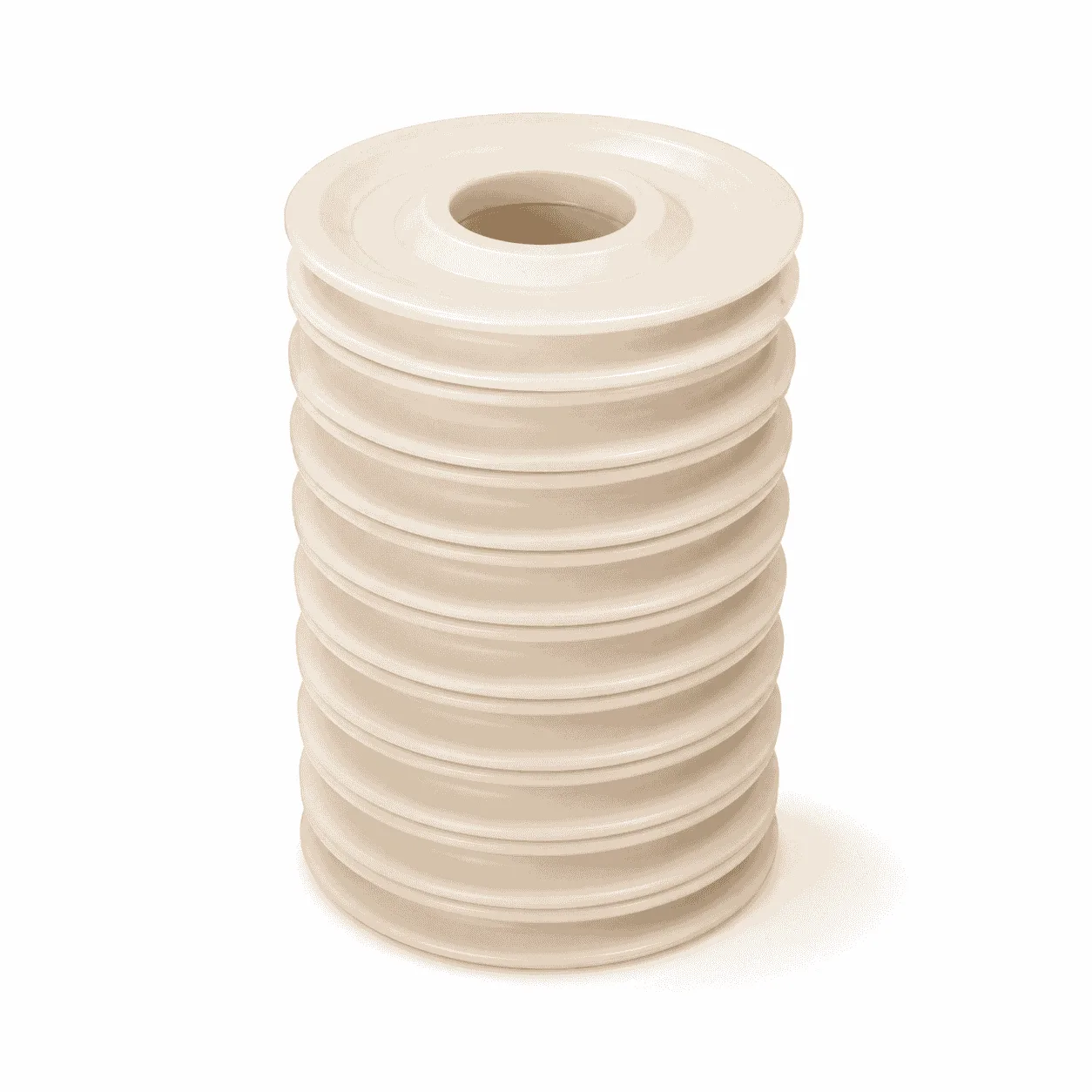
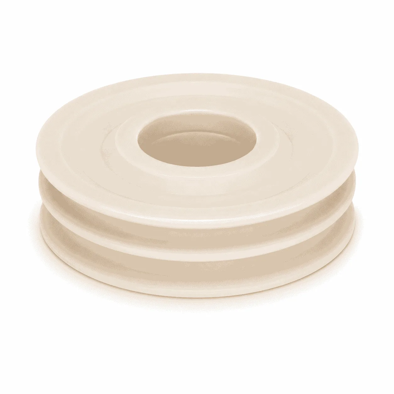
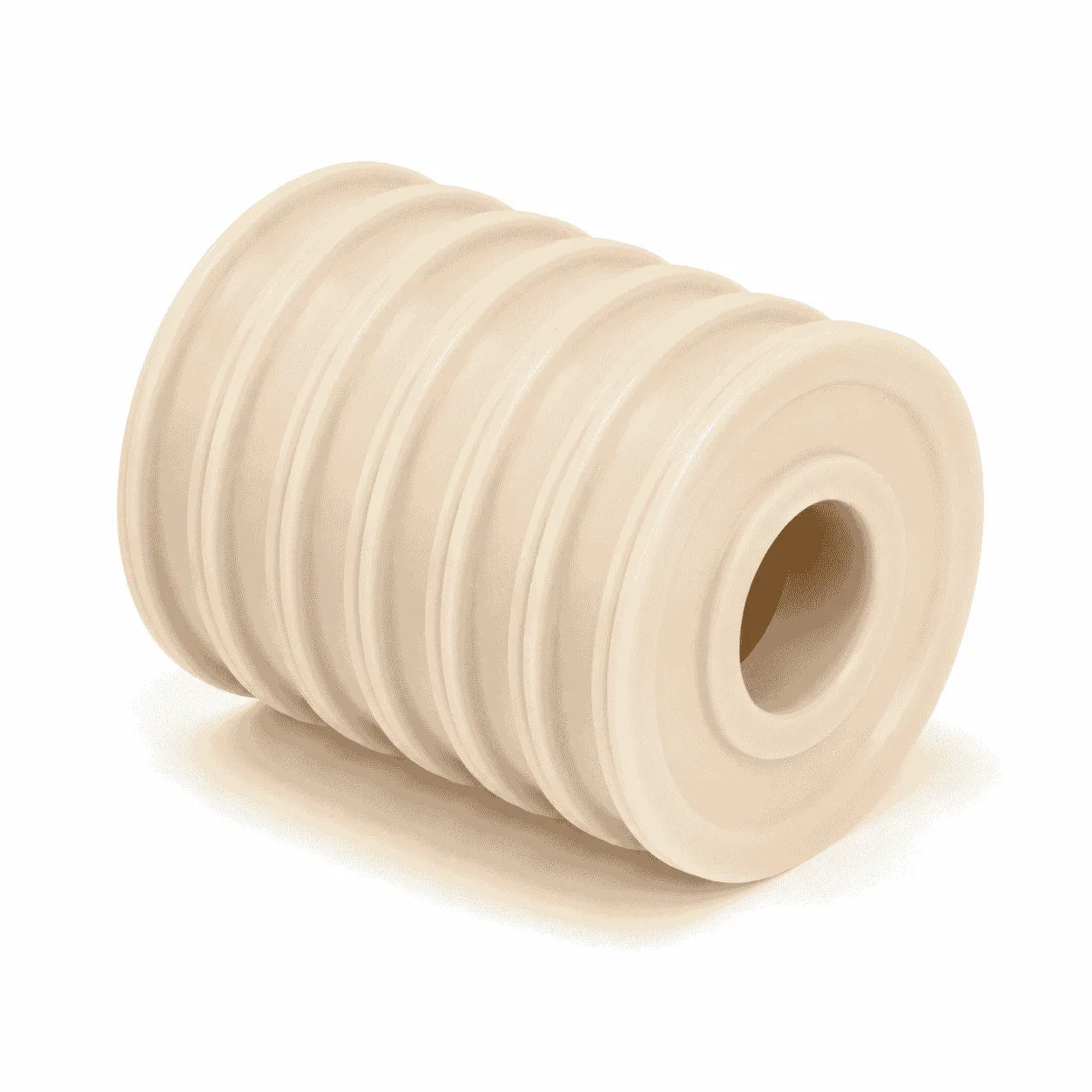
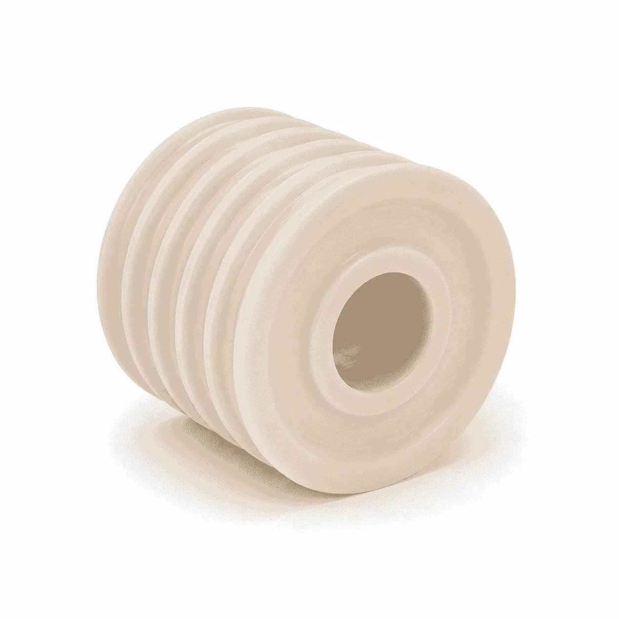
The CNC Machined Nylon Rope Guide Pulley is an engineering plastic wheel designed to guide, support or redirect wire ropes, cables and other flexible transmission elements in tower cranes, construction lifting equipment and industrial material-handling systems. The product shown in the image features a natural-colored nylon body, a precision-machined center bore, a deep circumferential rope groove and raised flanges on both sides.

The circumferential groove provides a defined running path for the rope and helps reduce unnecessary lateral movement when the rope changes direction. Depending on the equipment design, the pulley may be installed in an auxiliary rope-guiding mechanism, trolley travel system, luffing mechanism, positioning assembly, limit-control system or cable-routing structure.

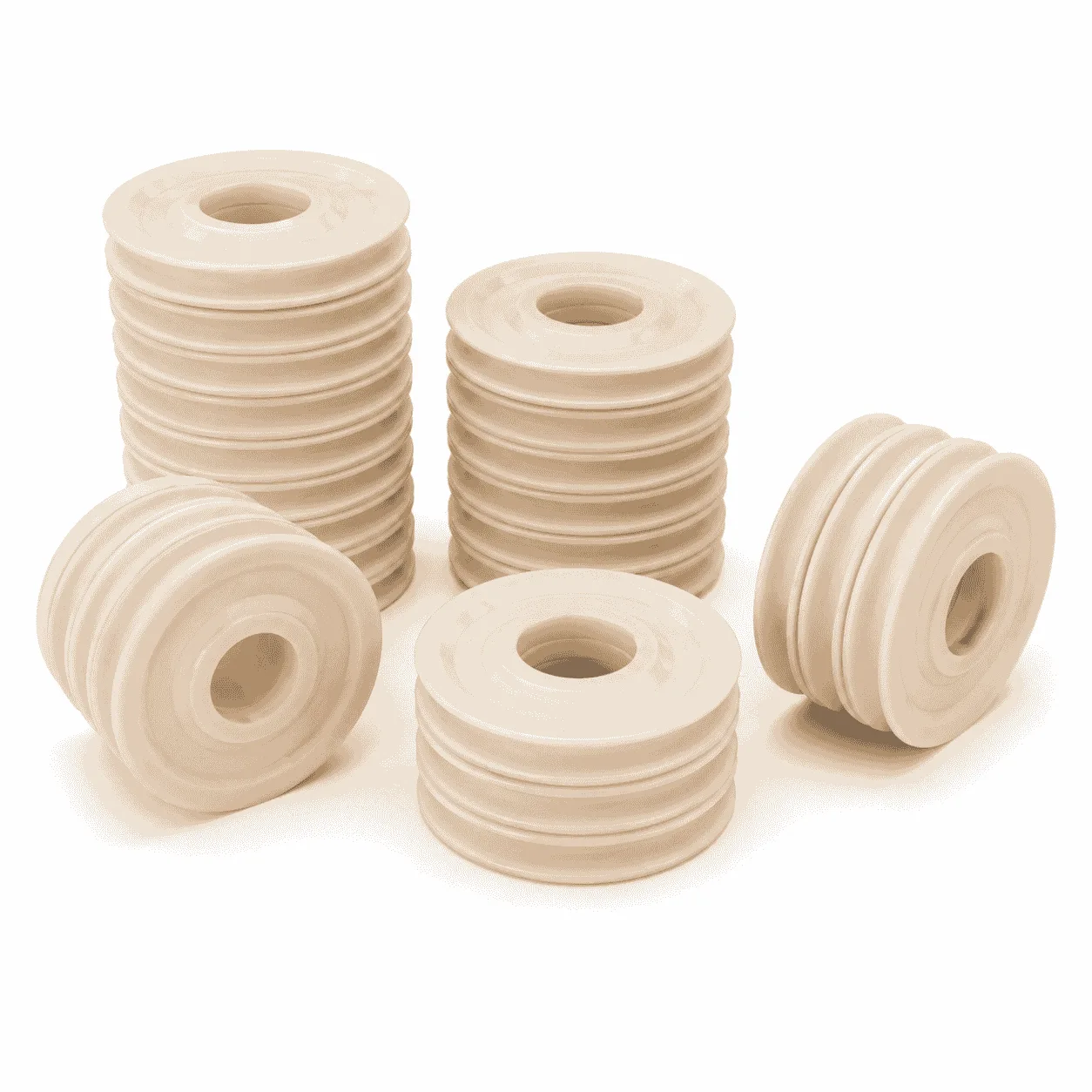
The pictured batch includes several pulley diameters and widths, indicating that the product can be manufactured for different wire-rope diameters, shaft sizes and installation spaces. The image does not confirm one universal tower crane model, nylon grade, bearing specification or rated load. Final dimensions and installation requirements must follow the approved drawing or measured sample.

How the CNC Machined Nylon Rope Guide Pulley Works

A pulley is a wheel mounted on an axle, shaft, bearing or bushing. A groove around its circumference locates the wire rope or cable while the wheel rotates. This structure allows the rope to change direction, remain aligned or move through a mechanical system with reduced sliding contact.

In tower crane and lifting-equipment assemblies, wire ropes may move during lifting, trolley travel, luffing, reeving or auxiliary positioning operations. A correctly designed guide pulley helps maintain the required rope path and reduces direct contact between the rope and surrounding brackets, frames or structural components.

The rope groove does not retain or carry the rope independently. Its main function is to provide a controlled rolling surface and lateral guidance. The groove width, depth, bottom radius and opening profile must be selected according to the rope diameter and operating angle.

A groove that is too narrow may squeeze the rope, create excessive friction and increase localized wear. A groove that is too wide may allow unstable rope tracking, lateral movement or contact with the pulley flanges.

Material Options for the CNC Machined Nylon Rope Guide Pulley

This product can be machined from Polyamide PA Nylon Rod. Suitable material options may include PA6 nylon, cast MC nylon, PA66 nylon, oil-filled nylon, MoS₂-filled nylon and other modified polyamide materials.

Nylon is a family of synthetic polymers containing repeating amide linkages. It is widely used for molded and machined mechanical components because different nylon grades can provide useful combinations of mechanical strength, toughness, wear resistance and machinability. General material information is available from the Wikipedia explanation of nylon.

PA6 may be considered for general-purpose machined guide pulleys requiring balanced toughness and wear performance. Cast MC nylon is commonly evaluated for larger pulleys, rollers, sleeves and structural components. PA66 may be selected where increased rigidity and mechanical strength are required.

Oil-filled nylon or MoS₂-modified nylon may be considered for applications involving repeated rotation, sliding contact or reduced external lubrication. The final material grade should be selected according to radial load, rotational speed, impact, temperature, humidity, outdoor exposure, contamination and required service life.

Product color cannot independently identify the nylon grade. Natural, blue, black or other colored nylon components may use different base materials and formulations. Material certificates or confirmed raw-material specifications should be used where a particular grade is required.

Nylon can absorb moisture and may undergo dimensional changes in humid or water-contact environments. This factor should be considered when machining close-fitting shaft bores, bearing seats and precision installation interfaces.

7 Amazing Benefits of the CNC Machined Nylon Rope Guide Pulley

  • Controlled rope guidance: the circumferential groove helps keep the wire rope or cable in its intended running position.
  • Reduced operating noise: nylon can reduce contact and impact noise compared with selected metal-to-metal arrangements.
  • Lower rotating weight: nylon pulley bodies are generally lighter than equivalent solid steel components.
  • Good wear performance: suitable nylon grades can withstand repeated rolling and guiding contact under approved operating conditions.
  • Corrosion-free pulley body: nylon does not rust like ordinary carbon steel when exposed to rain, humidity or routine equipment washing.
  • Flexible structural machining: grooves, bores, bearing seats, shoulders and retaining features can be produced according to drawings.
  • Consistent batch production: CNC machining helps control bore diameter, groove position, outside diameter and overall width across repeat orders.

Rope Groove Design and Compatibility

The groove is one of the most important structures of a CNC Machined Nylon Rope Guide Pulley. Its bottom radius should match the wire-rope or cable diameter without producing excessive compression or unstable contact.

Important groove parameters include the groove width, groove depth, bottom radius, opening angle, flange height and relationship between the groove centerline and mounting bore. These dimensions influence rope tracking, contact distribution and the risk of the rope leaving the intended running path.

The two side flanges should provide sufficient lateral guidance without continuously rubbing against the sides of the rope. Sharp groove edges should be avoided because they may create localized rope wear.

General information about pulley mechanisms and grooved wheels is available from the Wikipedia explanation of pulleys.

Center Bore and Installation Structures

The center bore may be manufactured as a straight shaft bore, stepped bore, metal-bushing seat or bearing seat. The appropriate structure depends on rotational speed, radial load, installation space, maintenance requirements and allowable running resistance.

  • Straight through bore
  • Stepped shaft bore
  • Ball-bearing mounting seat
  • Metal bushing or sleeve seat
  • Retaining-ring groove
  • Positioning shoulder
  • Keyway or locating groove
  • Threaded retaining structure

A plain-bore structure may be considered for selected low-speed guide positions. A bearing or metal bushing may be required where rotational speed, radial load or service-life requirements are higher.

The shaft fit should allow stable rotation without excessive looseness. Excessive clearance may produce vibration, impact and uneven groove wear, while insufficient clearance may make installation difficult or restrict rotation after moisture absorption.

CNC Machining Capabilities

Through our CNC Plastic Machining service, the CNC Machined Nylon Rope Guide Pulley can be produced by turning, boring, drilling, milling, grooving, tapping, chamfering and deburring.

Available machining dimensions and structures include:

  • Outside diameter
  • Overall pulley width
  • Center bore diameter
  • Groove width and depth
  • Groove bottom radius
  • Single-groove or multiple-groove structures
  • Flange thickness and edge radius
  • Stepped bores and bearing seats
  • Metal bushings and shaft sleeves
  • Retaining grooves and positioning shoulders

Products can be manufactured according to technical drawings, physical samples or verified installation dimensions. For replacement pulleys, providing the original pulley together with the shaft dimensions, wire-rope specification or equipment drawing helps reduce the risk of incorrect bore and groove dimensions.

Typical Application Positions

The pulley may be used in suitable rope-guiding and auxiliary routing positions in tower cranes, construction lifting equipment, winches and material-handling machinery.

  • Tower crane auxiliary rope-guiding assemblies
  • Trolley travel rope guide mechanisms
  • Luffing and positioning rope-routing systems
  • Limit-control rope guide assemblies
  • Construction hoist cable-guiding components
  • Winch and material-handling guide systems
  • Industrial cable and rope routing mechanisms
  • Low-noise replacements for selected metal guide wheels

A tower crane uses wire ropes, winches, sheaves and structural assemblies to lift and move materials. General information about cranes is available from the Wikipedia explanation of cranes.

Production and Quality Inspection

For batch production, the first finished pulley should be inspected before continuous machining. Important inspection dimensions include outside diameter, overall width, center bore diameter, groove width, groove depth, groove radius, concentricity and end-face runout.

The groove surface should be checked for burrs, sharp edges and excessive machining marks. Groove edges can be rounded or chamfered according to the drawing to reduce localized contact with the wire rope.

The center bore, bearing seat and retaining structures should remain clean and free from machining chips. Where bearings or metal bushings are installed, the fitting dimensions should be inspected before assembly.

During batch processing, dimensional sampling can help control variations caused by tool wear, material temperature and internal material stress. Finished products may be separated according to drawing number, pulley size, tower crane model or production batch.

Safety and Selection Requirements

A nylon rope guide pulley should not automatically be treated as a direct replacement for every steel crane sheave. Components used in main hoisting, load-bearing or other safety-critical positions require verified structural calculations, approved material data, appropriate bearings, safety factors and inspection procedures.

The final installation position should be reviewed before material and dimensional specifications are confirmed. Where the pulley directly supports a lifting load or affects wire-rope retention, the design should be reviewed and approved by the equipment manufacturer or a qualified engineer.

Routine inspection should check for groove wear, cracking, deformation, loose shaft fitting, restricted rotation and abnormal operating noise. Damaged or heavily worn components should be removed from service according to the equipment maintenance procedure.

Information Required Before Production

To manufacture the CNC Machined Nylon Rope Guide Pulley accurately, please provide the outside diameter, overall width, center bore diameter, groove width, groove depth, groove radius, nylon grade, shaft specification and required quantity.

Please also provide the tower crane model, installation position, wire-rope diameter, rotational speed, expected radial load, bearing model, working temperature and outdoor operating conditions where available.

The image is provided as an appearance and batch-production reference only. It does not establish a universal tower crane specification, load capacity, bearing type or nylon grade. Final dimensions, material, tolerances and installation requirements must follow the approved drawing, measured sample and equipment safety requirements.

Quality Control

Quality Control and Delivery Standards

Drawing & Material Check

Check drawings for full specifications and confirm materials according to service conditions to prevent product defects.

Machining Quality Control

Inspect all key processing steps and fully verify dimensions, holes, grooves and fitting surfaces.

Finishing & Batch Control

Deburr, chamfer and clean products for easy installation. Ensure uniform quality among batch products.

Packaging & Delivery

Choose appropriate packaging solutions based on product features to protect goods from collision, deformation and mixing during transit.

Processing Quality Control of Engineering Plastics Parts

Unlike metal parts, engineering plastic components still require strict control over dimensions, holes, edges, surface, materials and assembly performance for equipment use.

application

Applications for Engineering Plastic Parts

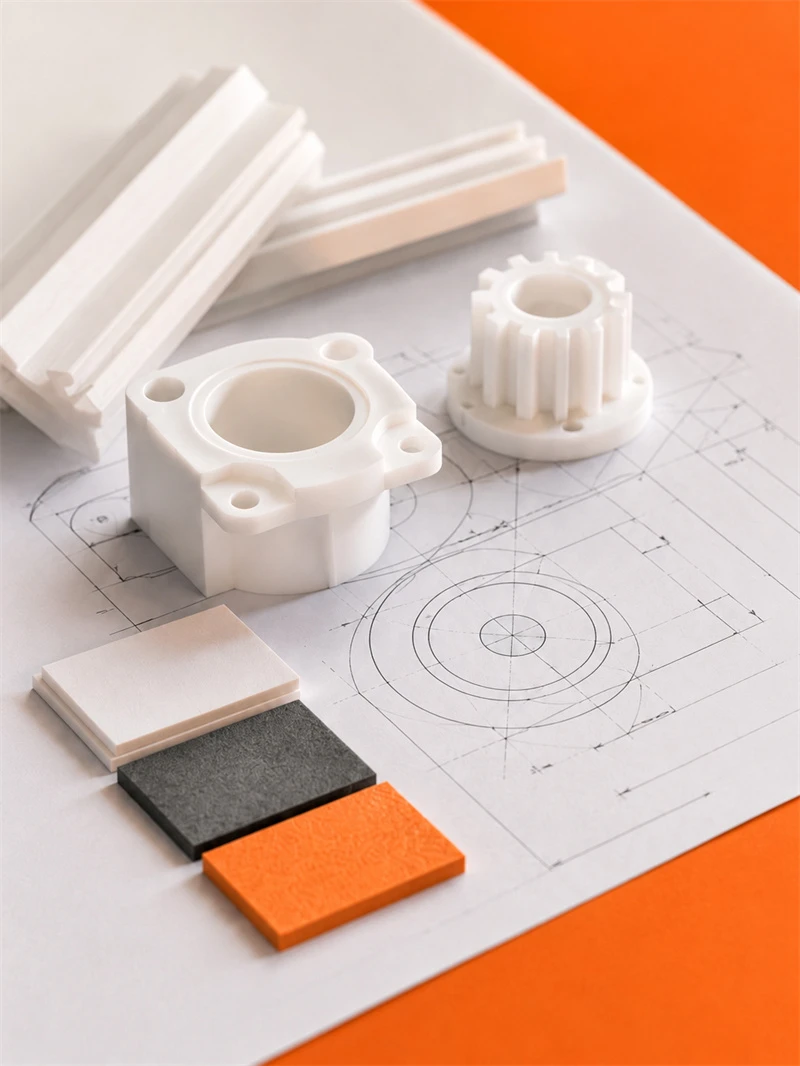
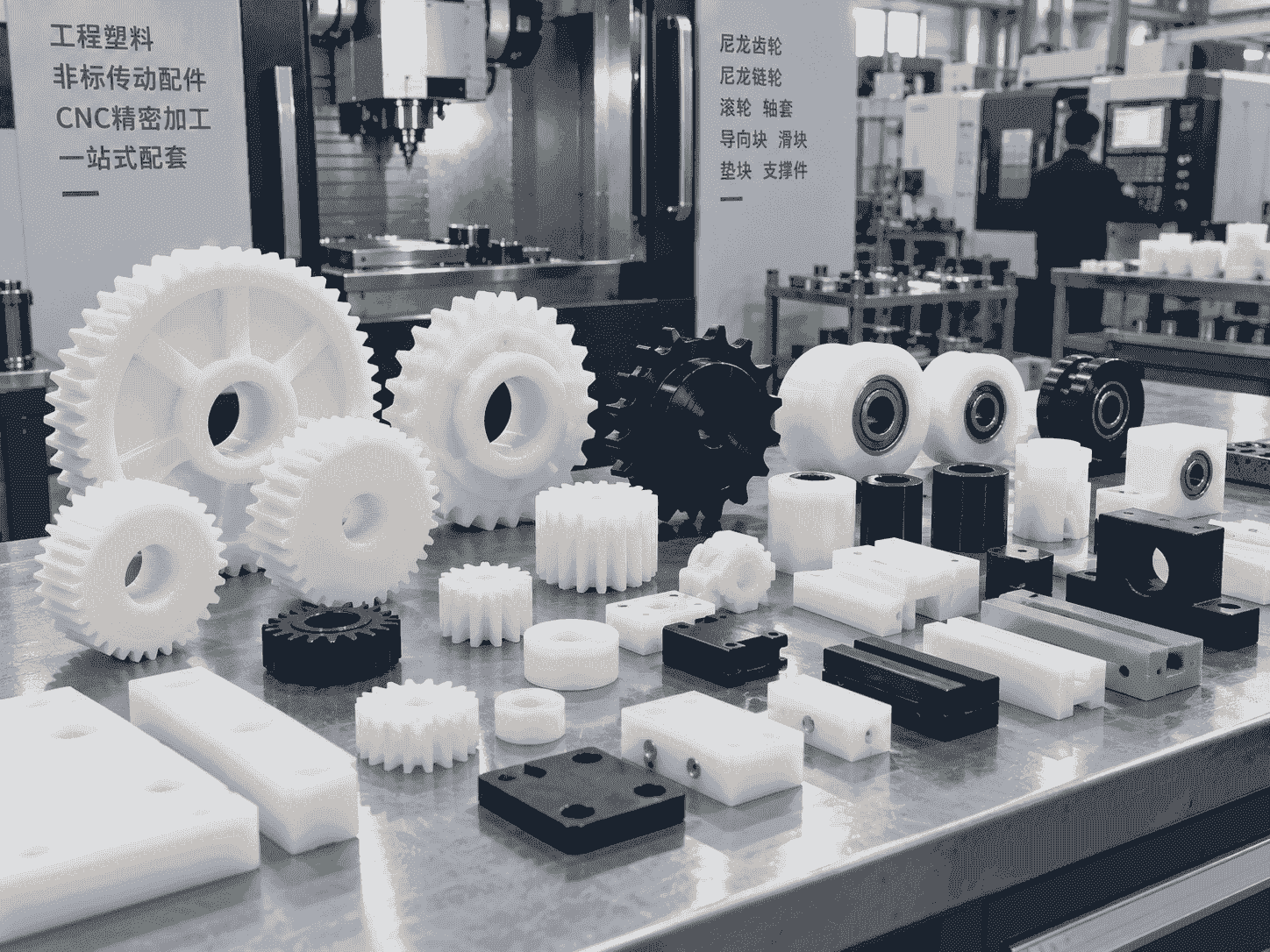
Engineering plastic parts suit friction, guide, support, buffer, anti-corrosion and insulation areas. We supply UHMWPE, POM, PA, PP/PE components for conveyor, food, mining, machinery, chemical and cable systems, with custom OEM service available.

Our Blog

Latest News & Knowledge

Stay updated with our latest industry insights, company updates and featured articles.

We Love to Hear From You

Need UHMWPE sheets & custom plastic machined/OEM parts?Send specs & material needs, free quote within 24h.