Heavy Duty UHMWPE Crane Load Spreader Pads

UHMWPE Crane Load Spreader Pads are reusable heavy-duty load-distribution panels featuring solid square construction, broad working surfaces, finished edges and integrated carrying holes. Practical reference sizes include 500 × 500 × 50 mm, 600 × 600 × 60 mm, 800 × 800 × 80 mm and 1000 × 1000 × 80 mm for mobile cranes, concrete pumps, boom trucks and hydraulic stabilizer equipment.

category Brand:
Share :

Description

Product Description

UHMWPE Crane Load Spreader Pads

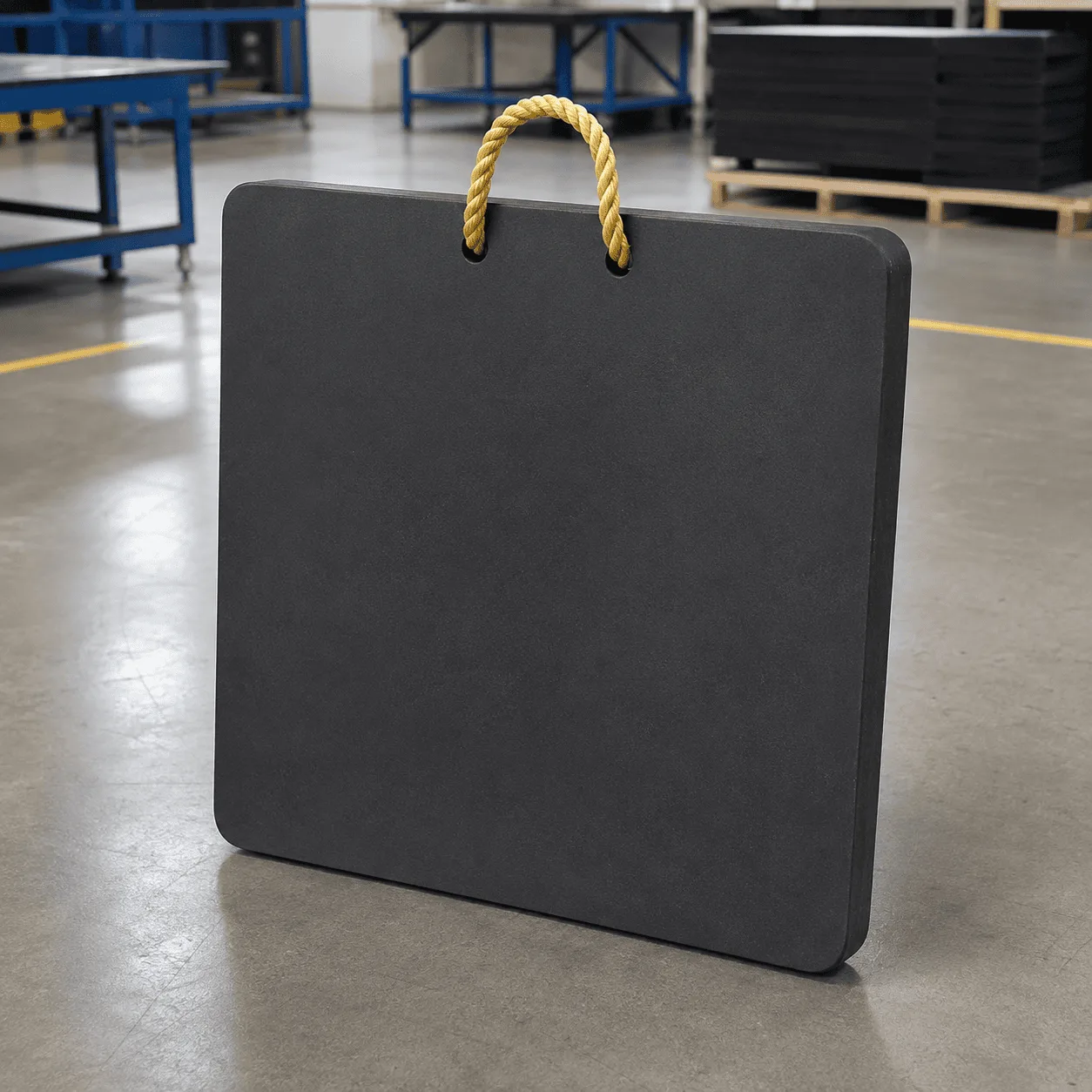
UHMWPE Crane Load Spreader Pads are heavy-duty engineering-plastic panels designed to provide a larger load-distribution area beneath mobile crane outriggers, concrete pump stabilizers, truck-mounted crane legs, boom trucks, aerial work platforms and other hydraulic support equipment.

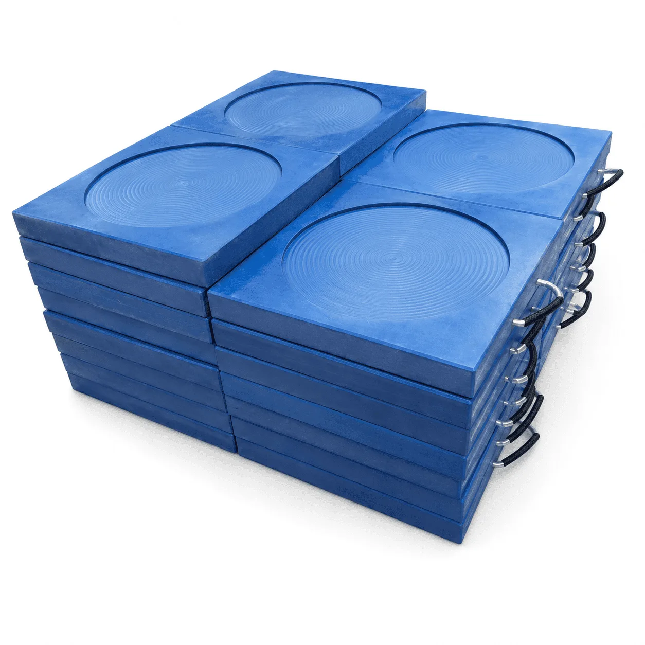
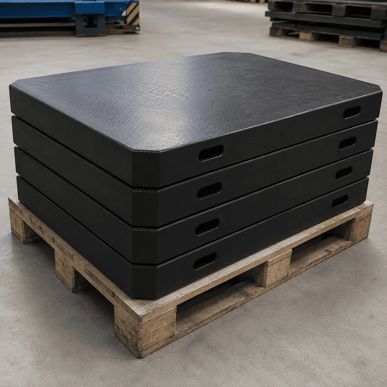
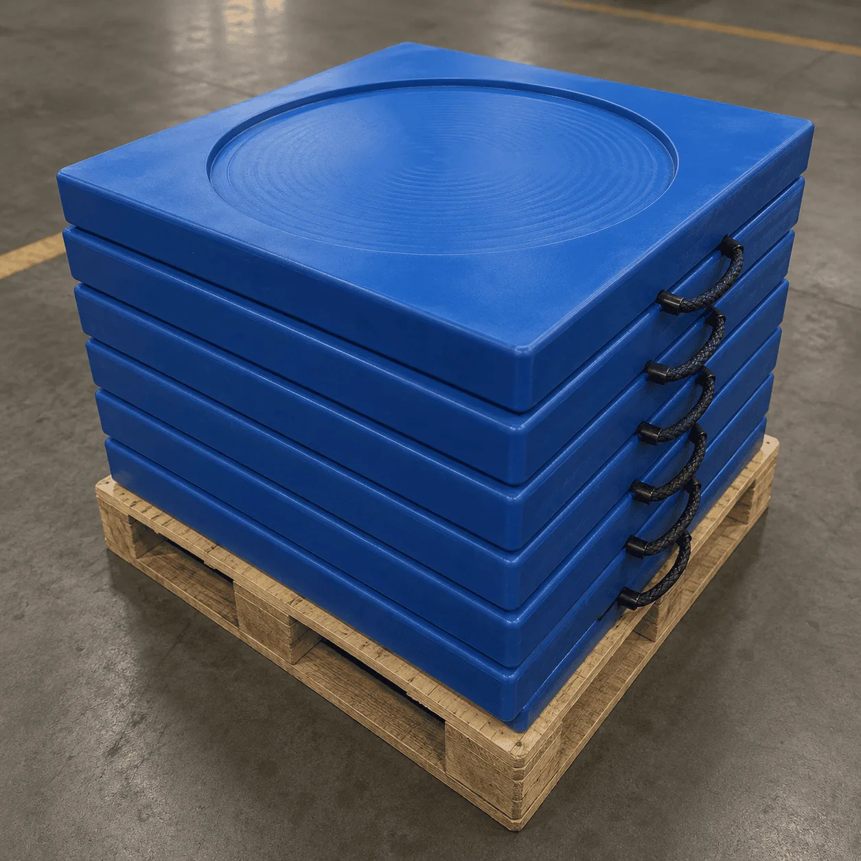
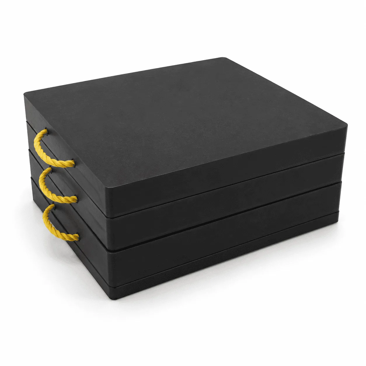
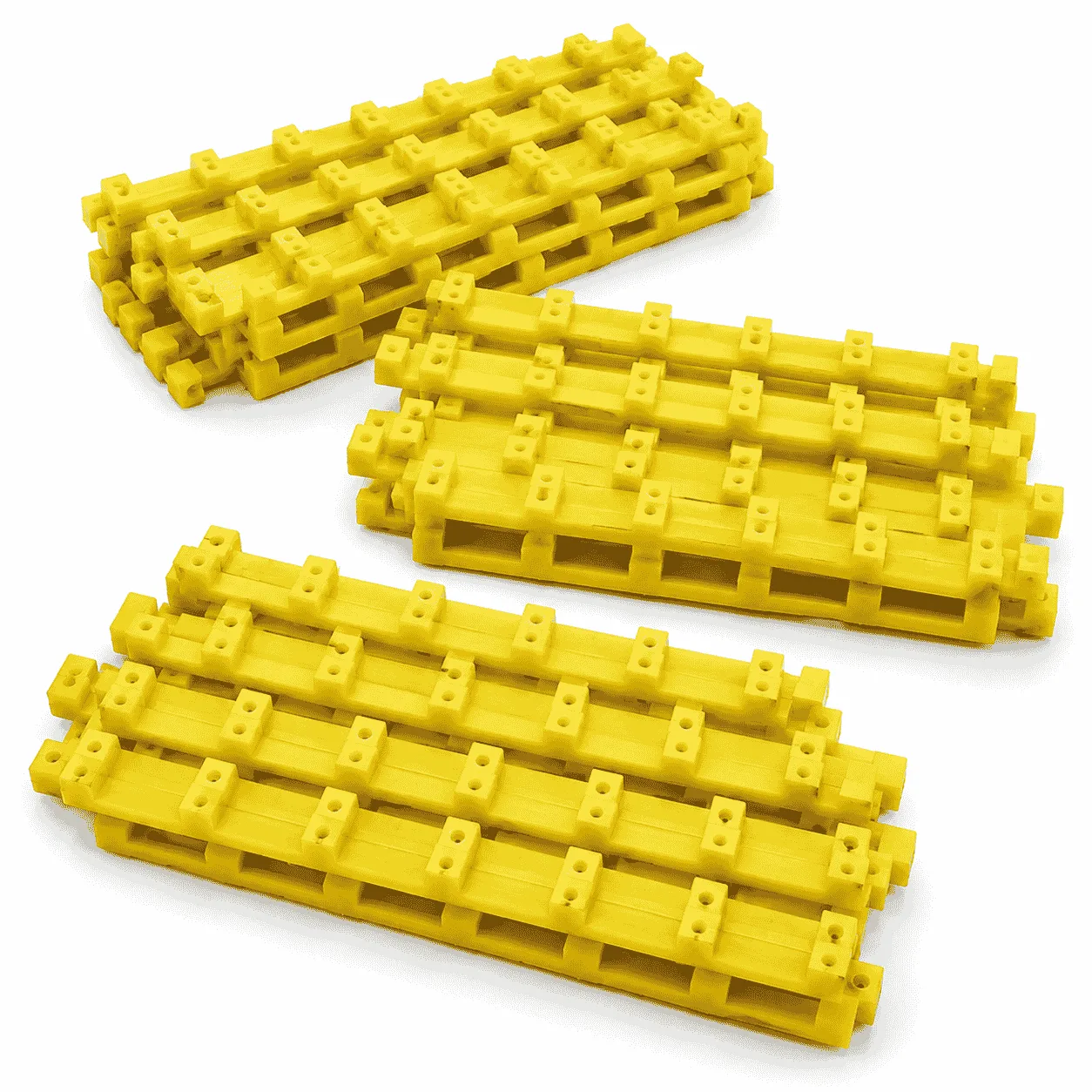
The product shown features a thick solid square structure, broad working surfaces, finished outside edges and integrated carrying holes positioned near the panel edges. Matching panels can be stacked together for transportation, vehicle storage, warehouse organization and repeated equipment setup.

The main purpose of the panel is to create a larger geometric contact area between the original equipment foot and the supporting surface. A properly selected load spreader pad can help transfer the individual stabilizer reaction over a broader footprint.

Unlike temporary access mats that are installed continuously to form a vehicle route, UHMWPE Crane Load Spreader Pads are normally positioned individually beneath each hydraulic stabilizer foot. The final panel dimensions and thickness must be selected according to the equipment reaction, original foot dimensions and condition of the surface below.

Reference Sizes of UHMWPE Crane Load Spreader Pads

The exact dimensions of the panels shown cannot be determined from the photograph alone. The following specifications are practical reference sizes for solid UHMWPE crane load-distribution panels.

Reference Specification Approximate Solid Weight Typical Application
400 × 400 × 40 mm Approximately 5.9–6.1 kg Compact hydraulic stabilizers and smaller service vehicles
500 × 500 × 50 mm Approximately 11.6–11.8 kg Utility vehicles, boom trucks and compact lifting equipment
600 × 600 × 60 mm Approximately 20–20.5 kg Mobile cranes and concrete pumping equipment
700 × 700 × 60 mm Approximately 27–28 kg Medium crane and hydraulic stabilizer applications
800 × 800 × 80 mm Approximately 47.5–48.5 kg Concrete pump trucks and medium heavy machinery
1000 × 1000 × 80 mm Approximately 74–76 kg Large mobile cranes and heavy-equipment stabilizers
1200 × 1200 × 100 mm Approximately 133–136 kg Large-format heavy-equipment support arrangements

The listed weights are theoretical references for substantially solid UHMWPE panels with a material density of approximately 0.93–0.94 g/cm³. Actual finished weight can vary according to carrying holes, edge machining, recessed areas, raw-material grade and production tolerances.

Compact specifications such as approximately 400 × 400 × 40 mm and 500 × 500 × 50 mm provide practical options where vehicle-storage space and repeated manual positioning are important.

Medium specifications such as approximately 600 × 600 × 60 mm, 700 × 700 × 60 mm and 800 × 800 × 80 mm provide broader geometric footprints for mobile cranes, concrete pumps, boom trucks and similar stabilizer-equipped machinery.

Large specifications such as approximately 1000 × 1000 × 80 mm and 1200 × 1200 × 100 mm can have substantial finished weights. Suitable transportation, storage and mechanical handling equipment may therefore be required.

These dimensions and weights are product references rather than universal safe-working-load ratings. Final permitted use must be confirmed according to the maximum individual stabilizer reaction, equipment-foot geometry, UHMWPE grade, loading duration, panel condition and supporting surface.

Main Product Specifications

Specification Typical Reference
Product type Crane load spreader and hydraulic stabilizer support panel
Primary material UHMWPE
Main construction Solid one-piece polyethylene panel
Main shape Square
Alternative shapes Rectangular, round or clipped-corner formats
Reference size range Approximately 400 × 400 mm to 1200 × 1200 mm
Reference thickness Approximately 40–100 mm
Working surface Flat or lightly finished surface
Handling options Integrated hand holes, rope handles or metal handles
Storage structure Stackable matching panels
Material options Virgin UHMWPE or controlled recycled UHMWPE
Main applications Cranes, concrete pumps, boom trucks and heavy machinery

Final length, width, thickness, outside shape, handle structure and raw-material grade should always be matched to the approved product drawing and actual equipment-support requirement.

Load-Distribution Function

The main function of UHMWPE Crane Load Spreader Pads is to provide a broader intermediate contact area beneath a hydraulic stabilizer foot.

A crane or heavy-equipment stabilizer can transfer a concentrated reaction through a relatively small original foot. The load spreader panel creates a larger geometric footprint beneath that foot.

The complete support arrangement depends on:

  • The maximum reaction at one stabilizer
  • The dimensions of the original equipment foot
  • The length and width of the panel
  • The thickness of the panel
  • The selected UHMWPE grade
  • The position of the equipment foot
  • The supporting ground or floor condition
  • The duration and direction of loading
  • The amount of support beneath the complete panel

A larger panel provides a larger geometric footprint, but outside dimensions alone do not establish a universal load rating.

Solid One-Piece Panel Structure

The product uses a solid one-piece UHMWPE panel rather than a structure assembled from multiple wooden or metal layers.

A solid panel structure can provide:

  • A broad working footprint
  • No welded panel joints
  • No assembled timber layers
  • Compatibility with round and square stabilizer feet
  • Multiple practical thickness options
  • A structure that is relatively easy to inspect
  • Convenient organization with matching panel sets

The stabilizer foot should remain within the intended central working area and should not be positioned close to an unsupported outside edge.

The panel should not bridge a deep opening, unstable edge, large unsupported void or unsuitable surface.

Square Load Spreader Design

The square panel shape makes efficient use of the available geometric support area and can be positioned beneath different equipment-foot shapes.

A square load spreader panel can provide:

  • A broad central equipment-contact area
  • Straight edges for organized stacking
  • Compatibility with round, square or rectangular support feet
  • Multiple practical length and thickness combinations
  • Convenient warehouse and vehicle storage
  • A simple format for routine inspection

The outside dimensions should be selected according to the required effective support area, original stabilizer-foot size and allowable pressure of the supporting surface.

Flat Working Surface

The working face can be produced as a flat or lightly finished solid surface.

A flat working surface can provide:

  • A simple equipment-contact area
  • Broad contact with compatible stabilizer feet
  • Convenient cleaning after use
  • Easy visual inspection
  • Organized stacking with matching panels
  • Compatibility with different equipment-foot shapes

The working surface should be cleaned before the equipment reaction is applied. Mud, oil, gravel, metal fragments and other hard objects can affect the contact between the stabilizer foot and the panel.

The surface structure does not replace correct panel sizing, proper foot positioning or suitable supporting conditions.

Finished Edges and Corners

The outside edges can be machined or finished according to the selected panel dimensions and handling requirements.

Available edge structures may include:

  • Straight finished edges
  • Rounded outside corners
  • Clipped or chamfered corners
  • Machined edge radii
  • Finished carrying-hole edges

Finished outside edges make the panels easier to handle, stack, clean and inspect during repeated industrial use.

The corners and outside edges should be checked regularly for cracks, deep cuts, excessive wear and permanent deformation.

Integrated Carrying Holes

The reference products include integrated carrying holes positioned close to the outside edges.

These openings provide defined gripping areas when individual panels need to be:

  • Removed from vehicle storage
  • Moved toward an individual stabilizer position
  • Adjusted before equipment loading
  • Recovered after operation
  • Stacked with matching panels
  • Returned to a vehicle or warehouse

Before moving a panel, inspect:

  • The complete carrying-hole edge
  • The UHMWPE material surrounding the opening
  • Visible cracks or deep cuts
  • Permanent deformation
  • Sharp damage that may affect handling
  • Excessive wear around the gripping area

The carrying holes are intended for routine transportation and positioning. They should not automatically be treated as certified lifting points for suspending a panel or a complete stack.

Large or thick panels may require two-person handling or suitable mechanical equipment regardless of the carrying-hole structure.

Optional Carrying Structures

Different carrying structures can be selected according to the panel dimensions and finished weight.

Available options may include:

  • Integrated machined hand holes
  • Braided rope handles
  • Rope handles with protective sleeves
  • Flexible synthetic carrying handles
  • Metal carrying handles

Each carrying structure should be inspected before use for cuts, wear, bending, looseness or damage around the attachment area.

Carrying handles assist transportation and positioning. They are not structural components carrying the crane stabilizer reaction.

Stackable Panel Design

The reference image shows multiple matching panels stacked together as a complete equipment-support set.

A stackable structure can help with:

  • Keeping matching panel dimensions together
  • Organizing vehicle and warehouse storage
  • Checking quantities before equipment setup
  • Confirming that every panel has been recovered
  • Separating different panel thicknesses
  • Separating virgin and recycled material products
  • Preparing complete sets for transportation

Stacking panels for storage does not mean multiple flat panels can automatically be stacked beneath an operating stabilizer.

Any multi-layer arrangement should be evaluated according to the applied reaction, panel alignment, total support height, contact between layers and possible lateral movement.

UHMWPE Material Properties

UHMWPE stands for ultra-high-molecular-weight polyethylene. It is a thermoplastic polyethylene containing extremely long molecular chains.

For a general material explanation, see the Wikipedia article about ultra-high-molecular-weight polyethylene.

Practical UHMWPE characteristics for load-spreader products include:

  • High toughness and impact resistance
  • Strong resistance to abrasive contact
  • Extremely low moisture absorption
  • Low coefficient of friction
  • Resistance to many acids and alkalis
  • Resistance to many corrosive chemical substances
  • Solid plastic construction that will not rust
  • Reusable performance for repeated industrial handling

UHMWPE can be considered where the panels will be repeatedly transported, positioned, loaded, recovered and exposed to wet or abrasive operating environments.

Finished product performance can vary according to molecular weight, raw-material grade, manufacturing process, panel dimensions, operating temperature and loading duration.

Chemical resistance should not be interpreted as universal resistance to every substance. Compatibility depends on the chemical, concentration, exposure time, temperature and selected UHMWPE grade.

Virgin and Recycled UHMWPE Options

Depending on the intended equipment-support application, the panels can be produced from virgin UHMWPE or controlled recycled UHMWPE.

Comparison Item Virgin UHMWPE Recycled UHMWPE
Raw-material source New controlled UHMWPE resin Reprocessed polyethylene feedstock
Color consistency Generally more consistent May vary between batches
Property consistency Generally easier to control Requires stronger batch inspection
Surface appearance Usually more uniform May show color or texture variation
Typical selection Applications requiring controlled material performance Selected general industrial support applications
Final approval According to grade and technical data According to batch properties and test results

The final material option should be selected according to the stabilizer reaction, required service life, environmental exposure and applicable technical requirements.

Impact and Wear Performance

UHMWPE Crane Load Spreader Pads may be repeatedly transported, positioned, loaded, recovered and stacked.

During regular operation, the panels may experience:

  • Repeated contact with hydraulic stabilizer feet
  • Impact during placement and recovery
  • Dragging across hard surfaces
  • Contact with gravel, sand and mud
  • Repeated stacking during transportation
  • Outdoor weather exposure
  • Regular washing and cleaning

The toughness and abrasion resistance of UHMWPE make it suitable for reusable industrial load-distribution components.

Panels showing visible cracks, severe permanent deformation, deep cuts, damaged carrying holes or excessive surface wear should be separated and evaluated before returning to demanding service.

Low Moisture Absorption

Crane load spreader panels are frequently exposed to rain, wet surfaces, mud, washing water and humid storage environments.

UHMWPE absorbs very little moisture compared with conventional wooden support boards and does not rust like an unprotected steel plate.

The panels should still be cleaned after wet or muddy use so that the upper surface, lower surface, outside edges and carrying holes can be properly inspected.

Corrosion-Resistant Plastic Construction

Solid UHMWPE panels do not experience the same rusting process as unprotected steel support plates.

This can reduce maintenance associated with:

  • Rust removal
  • Protective surface painting
  • Corrosion around exposed steel surfaces
  • Moisture absorption associated with wooden boards
  • Splintering associated with damaged timber products

Optional metal handles, fasteners or identification plates should still be inspected for corrosion, bending, looseness and mechanical damage.

How to Select UHMWPE Crane Load Spreader Pads

The correct panel should not be selected only according to total machine weight or maximum crane lifting capacity.

Individual stabilizer reactions can change according to:

  • Boom direction
  • Working radius
  • Lifted load
  • Outrigger extension
  • Equipment geometry
  • Operating configuration

Important selection information includes:

  • Maximum reaction at one stabilizer
  • Original equipment-foot dimensions
  • Required effective support area
  • Allowable pressure of the supporting surface
  • Required panel length and width
  • Required panel thickness
  • UHMWPE raw-material grade
  • Operating temperature
  • Duration of loading
  • Transportation and handling requirements

Each stabilizer position should be evaluated independently because reactions and supporting conditions can differ around the same machine.

Why Panel Thickness Matters

Two load spreader panels with identical outside dimensions can respond differently when their thicknesses are different.

For example, a 600 × 600 mm panel may be supplied as:

  • 600 × 600 × 40 mm
  • 600 × 600 × 50 mm
  • 600 × 600 × 60 mm
  • 600 × 600 × 70 mm

An 800 × 800 mm panel may be supplied as:

  • 800 × 800 × 50 mm
  • 800 × 800 × 60 mm
  • 800 × 800 × 70 mm
  • 800 × 800 × 80 mm

A 1000 × 1000 mm panel may be supplied as:

  • 1000 × 1000 × 60 mm
  • 1000 × 1000 × 80 mm
  • 1000 × 1000 × 100 mm

Panel thickness can affect:

  • Structural stiffness
  • Finished product weight
  • Manual or mechanical handling requirements
  • Vehicle-storage space
  • Response beneath the stabilizer foot
  • Long-term deformation under sustained loading

The thickest available panel is not automatically the correct choice. Final selection should balance equipment reaction, support conditions, stiffness, finished weight and handling requirements.

Applications of UHMWPE Crane Load Spreader Pads

UHMWPE Crane Load Spreader Pads can be used with different types of stabilizer-equipped machinery.

  • Mobile cranes
  • Truck-mounted cranes
  • Knuckle boom cranes
  • Concrete pump trucks
  • Boom pumps
  • Aerial work platforms
  • Cherry pickers and boom lifts
  • Utility service vehicles
  • Fire and rescue vehicles
  • Tree-care equipment
  • Vehicle-mounted work platforms
  • Maintenance vehicles
  • Heavy machinery stabilizers
  • Temporary machinery-support applications

The final panel dimensions, thickness and UHMWPE grade should always be matched to the actual equipment-support point.

Correct Equipment-Foot Positioning

Before applying equipment load, confirm that:

  • The panel is positioned correctly
  • The equipment foot remains within the main working area
  • The foot is not located close to an unsupported edge
  • The panel is not spanning a large unsupported void
  • The lower surface is appropriately supported
  • Large stones or hard objects are not trapped beneath the panel
  • The support point is not close to an unstable edge

The working surface should remain free from excessive oil, mud, gravel, metal fragments and other hard debris.

Inspection Before Every Use

Reusable load spreader panels should be inspected before every demanding equipment setup.

Check:

  • The upper working surface
  • The lower support surface
  • The outside edges and corners
  • The integrated carrying holes
  • The material surrounding each carrying hole
  • Visible cracks or permanent deformation
  • Deep cuts, gouges or excessive wear
  • Damage caused by concentrated equipment-foot contact

A damaged panel should be separated and evaluated before returning to crane or heavy-equipment service.

Cleaning, Storage and Transportation

After operation, remove mud, sand, gravel, oil and other contaminants from the upper and lower surfaces.

During storage:

  • Keep matching panel sizes and thicknesses together
  • Avoid unstable panel stacks
  • Remove hard debris before stacking
  • Separate damaged panels
  • Inspect carrying holes before moving the products
  • Use suitable lifting equipment for large-format panels
  • Keep different UHMWPE grades clearly identified

Related UHMWPE Products

Explore more UHMWPE engineering plastic products for crane support, heavy-equipment stabilization, ground protection and industrial applications.

7 Best Proven Benefits of UHMWPE Crane Load Spreader Pads

  • A broad panel footprint helps distribute concentrated equipment reactions
  • Solid one-piece UHMWPE construction provides a practical support structure
  • High toughness and impact resistance suit repeated industrial handling
  • Strong abrasion resistance supports reusable operation
  • Extremely low moisture absorption suits outdoor environments
  • Integrated carrying holes assist movement and organized storage
  • Multiple practical dimensions and thicknesses are available

Why Choose UHMWPE Crane Load Spreader Pads?

UHMWPE Crane Load Spreader Pads provide a practical load-distribution solution for mobile cranes, concrete pumps, boom trucks and other hydraulic stabilizer equipment.

The product combines a solid UHMWPE panel, a broad square footprint, finished outside edges, integrated carrying holes and a stackable structure.

Typical reference specifications include approximately 400 × 400 × 40 mm, 500 × 500 × 50 mm, 600 × 600 × 60 mm, 700 × 700 × 60 mm, 800 × 800 × 80 mm and 1000 × 1000 × 80 mm.

Final dimensions, thickness, material grade and permitted use should always be confirmed according to the maximum individual stabilizer reaction, equipment-foot geometry, supporting surface condition and actual operating requirements.

Quality Control

Quality Control and Delivery Standards

Drawing & Material Check

Check drawings for full specifications and confirm materials according to service conditions to prevent product defects.

Machining Quality Control

Inspect all key processing steps and fully verify dimensions, holes, grooves and fitting surfaces.

Finishing & Batch Control

Deburr, chamfer and clean products for easy installation. Ensure uniform quality among batch products.

Packaging & Delivery

Choose appropriate packaging solutions based on product features to protect goods from collision, deformation and mixing during transit.

Processing Quality Control of Engineering Plastics Parts

Unlike metal parts, engineering plastic components still require strict control over dimensions, holes, edges, surface, materials and assembly performance for equipment use.

application

Applications for Engineering Plastic Parts

Engineering plastic parts suit friction, guide, support, buffer, anti-corrosion and insulation areas. We supply UHMWPE, POM, PA, PP/PE components for conveyor, food, mining, machinery, chemical and cable systems, with custom OEM service available.

Our Blog

Latest News & Knowledge

Stay updated with our latest industry insights, company updates and featured articles.

We Love to Hear From You

Need UHMWPE sheets & custom plastic machined/OEM parts?Send specs & material needs, free quote within 24h.