Heavy Duty UHMWPE Grooved Crane Outrigger Pads

Grooved Crane Outrigger Pads are durable UHMWPE support panels featuring deep diagonal surface grooves, square structures and rounded edges. Typical sizes include 400 × 400 × 30–50 mm, 500 × 500 × 30–60 mm, 600 × 600 × 40–60 mm and 800 × 800 × 40–80 mm. The reusable pads are suitable for mobile cranes, concrete pumps, boom trucks and other outrigger-equipped machinery.

category Brand:
Share :

Description

Product Description

Grooved Crane Outrigger Pads

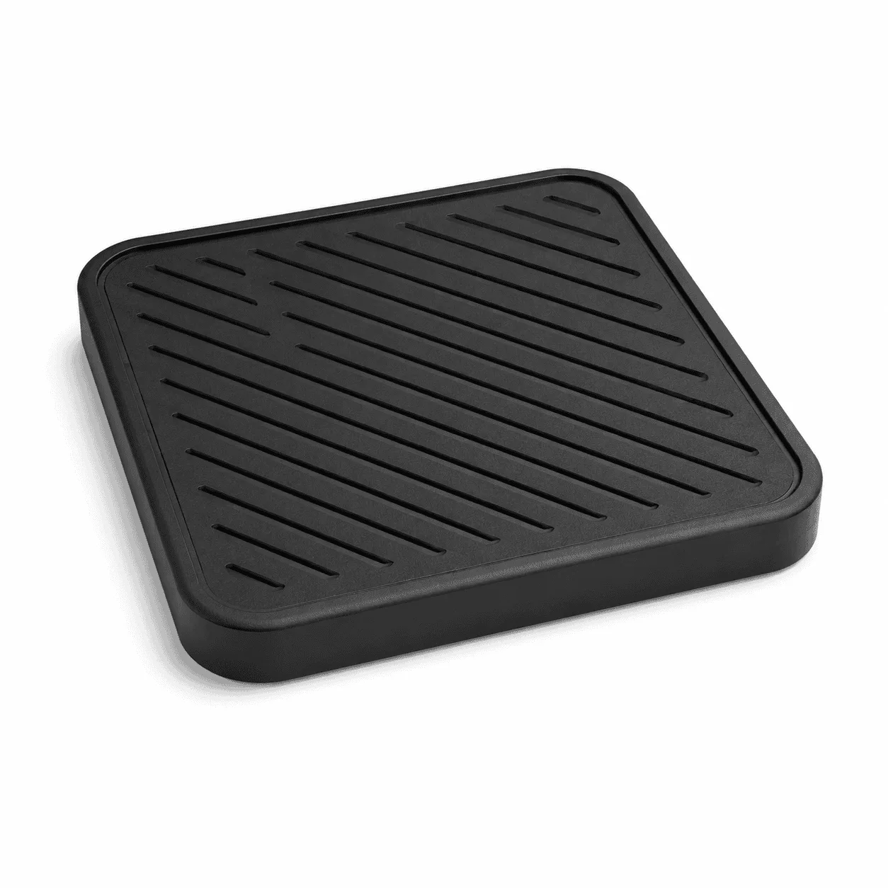
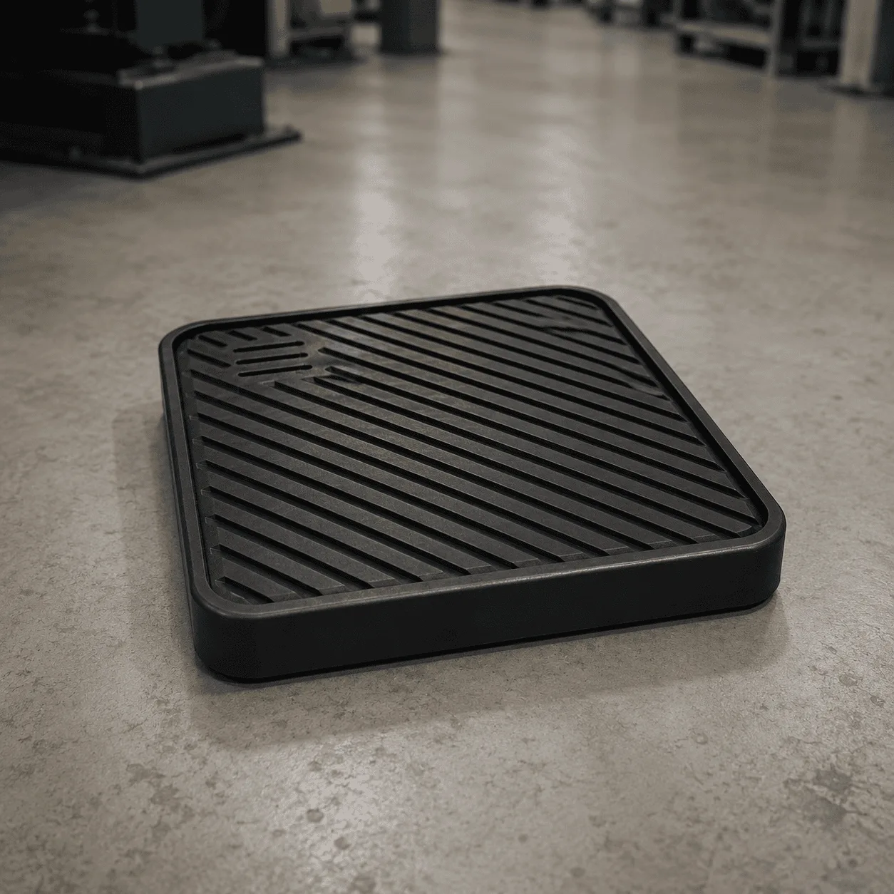
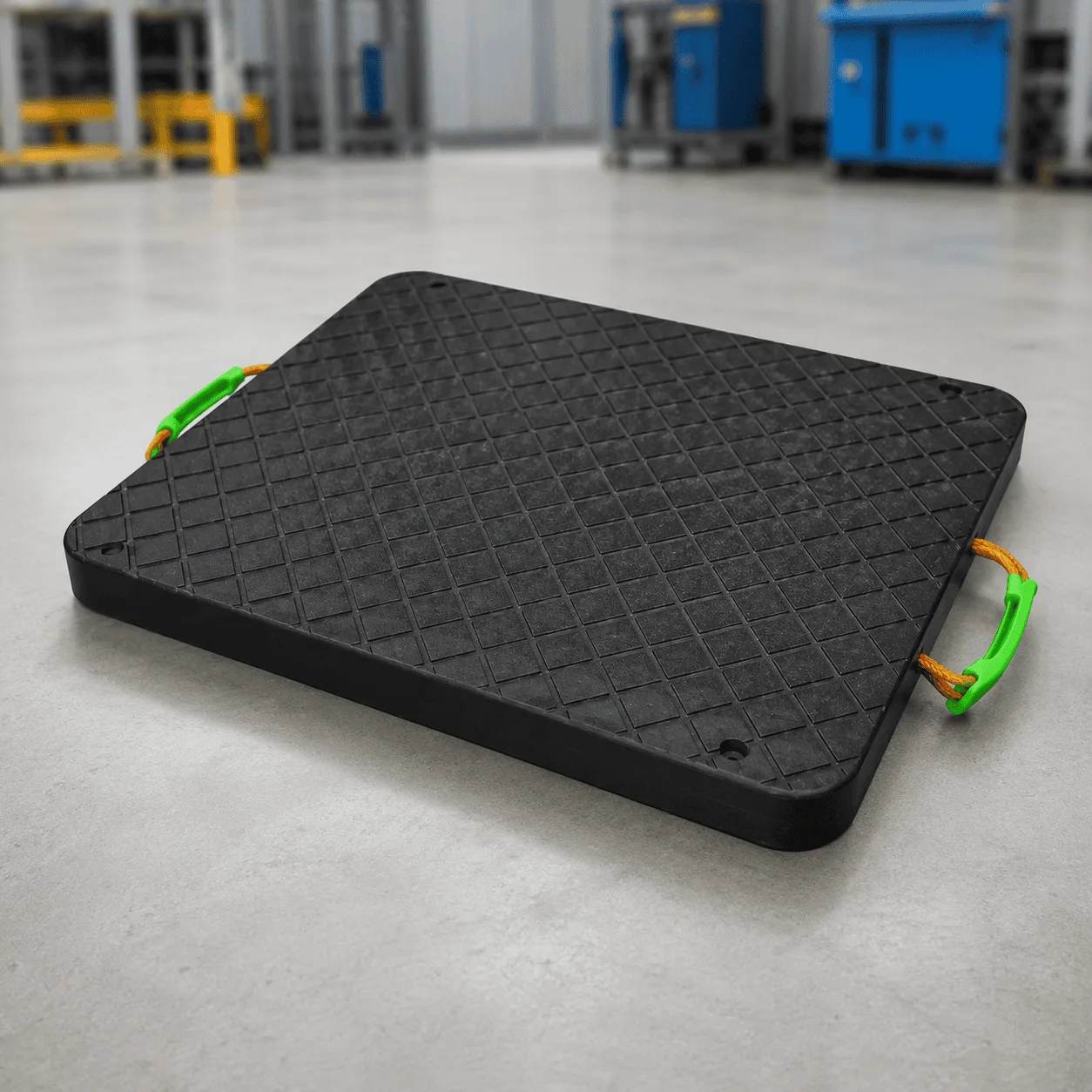
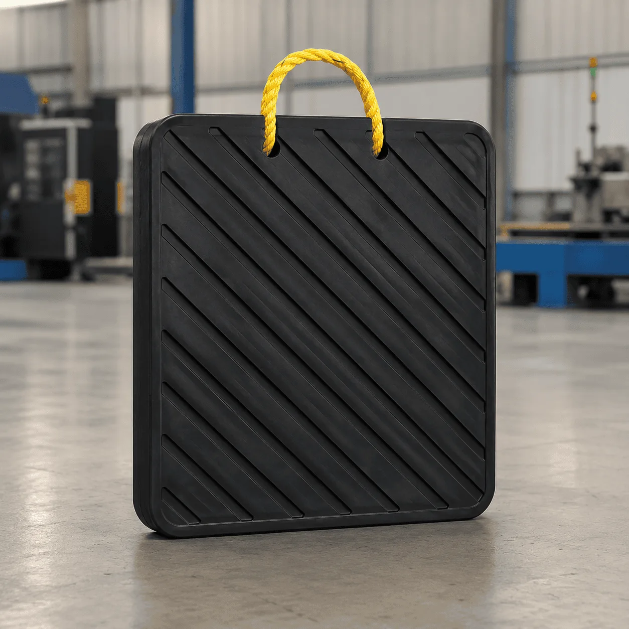
Grooved Crane Outrigger Pads are heavy-duty UHMWPE support panels designed to increase the effective contact area beneath mobile crane outriggers, concrete pump stabilizers, boom truck support legs, utility vehicles, lifting equipment, and other outrigger-equipped machinery. The product shown features a solid square structure, rounded outside edges, and distinctive diagonal grooves across the main working surface.

The grooved surface is the most recognizable feature of this pad design. Unlike a completely smooth support plate or a fine rough-textured pad, the surface uses clearly defined channels arranged across the panel. This creates a different working surface for equipment support applications where a visible and durable groove pattern is preferred.

The black UHMWPE construction provides a practical combination of wear resistance, impact resistance, low water absorption, and repeated outdoor usability. The square shape also makes complete equipment sets easier to arrange during transportation, stacking, storage, and repeated setup.

Unlike temporary roadway mats, which are installed continuously to create vehicle access routes, these pads are positioned directly beneath individual outriggers or stabilizer feet. Their primary purpose is to create a larger effective support area between the equipment and the underlying surface.

Typical Sizes of Grooved Crane Outrigger Pads

Grooved Crane Outrigger Pads can be supplied in different square dimensions and thicknesses according to the maximum individual outrigger reaction, original stabilizer foot dimensions, required support area, ground condition, material stiffness, handling method, and equipment configuration.

The original product family includes a particularly wide dimensional range. Practical reference specifications include:

Reference Pad Size Practical Thickness Range Typical Application
300 × 300 mm 20–40 mm Compact stabilizers and smaller support applications
400 × 400 mm 30–50 mm Light equipment and utility vehicle support
500 × 500 mm 30–60 mm General portable outrigger support
600 × 600 mm 40–60 mm General crane and equipment stabilizers
800 × 800 mm 40–80 mm Medium heavy equipment applications
1000 × 1000 mm 50–100 mm Large stabilizer and outrigger support
1500 × 1500 mm 80–150 mm Large heavy-equipment support systems
2000 × 2000 mm 100–200 mm Special large-format industrial applications

These dimensions are practical reference ranges rather than a universal size-and-capacity chart. Final thickness depends on the UHMWPE material structure, individual outrigger reaction, original support foot dimensions, required ground pressure reduction, pad rigidity, and complete operating conditions.

The approximately 500 × 500 × 40–50 mm format is practical for compact equipment support where portability and vehicle storage are important.

The approximately 600 × 600 × 40–60 mm format provides a balance between support area, product weight, repeated handling, and general crane applications.

The approximately 800 × 800 × 50–60 mm format provides a broader support footprint for larger equipment stabilizers.

Larger formats such as approximately 1000 × 1000 × 60–100 mm, 1500 × 1500 × 80–150 mm, and 2000 × 2000 × 100–200 mm require careful engineering review and suitable mechanical handling because product weight and structural requirements increase significantly with dimensions and thickness.

Main Product Specifications

Specification Typical Reference
Product type Grooved crane and equipment outrigger support pad
Primary material UHMWPE
Main shape Square
Reference color Black
Other practical colors Yellow, red, blue and project-specific colors
Upper surface Deep diagonal groove pattern
Edge structure Rounded corners and finished edges
Common size range Approximately 300 × 300 mm to 2000 × 2000 mm
Common thickness range Approximately 20–200 mm depending on pad size and application
Main applications Cranes, concrete pumps, boom trucks and stabilizer-equipped machinery

Final dimensions, thickness, material grade, groove depth, surface pattern, edge design, and handling features should always be selected according to the actual equipment and operating requirements.

Deep Diagonal Groove Surface

The most important visual and functional feature of Grooved Crane Outrigger Pads is the deep diagonal pattern across the main working surface.

Instead of using a completely flat or lightly textured plastic face, the pad includes clearly defined grooves running across the surface.

This structure can provide:

  • A clearly identifiable working surface
  • More pronounced texture than a smooth UHMWPE panel
  • Defined channels across the pad surface
  • A practical industrial surface for repeated equipment setup
  • Easy visual differentiation from standard flat outrigger pads

The groove structure should not be treated as a substitute for correct product sizing, stable ground, appropriate material thickness, or correct stabilizer positioning.

Before equipment loading, large stones, metal fragments, timber pieces, and other hard objects should be removed from the pad and supporting surface.

Grooved Surface Compared with a Rough Surface

A grooved support pad and a rough-textured support pad are not exactly the same product design.

A rough surface normally uses fine texture across most of the panel.

A grooved surface uses larger and more clearly defined channels.

The diagonal groove design may be preferred where:

  • A pronounced industrial surface pattern is required
  • The pad is frequently used outdoors
  • Operators need to identify the primary working surface quickly
  • The equipment is repeatedly repositioned
  • A deeper surface structure is preferred over fine texture

The correct surface design depends on the equipment foot, pad dimensions, supporting surface, operating environment, and complete setup requirements.

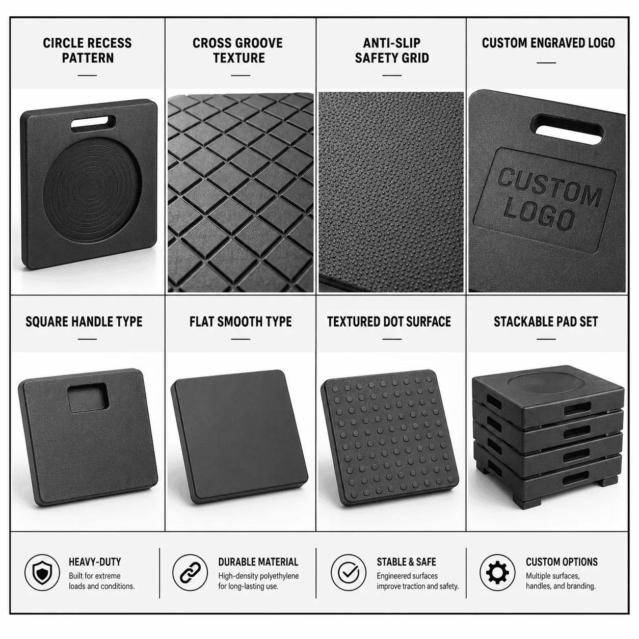
Multiple Groove Pattern Options

The wider outrigger pad product family can include different working surface structures.

Typical options may include:

  • Diagonal groove surfaces
  • X-groove surfaces
  • Cross-pattern grooves
  • Safety-grind textures
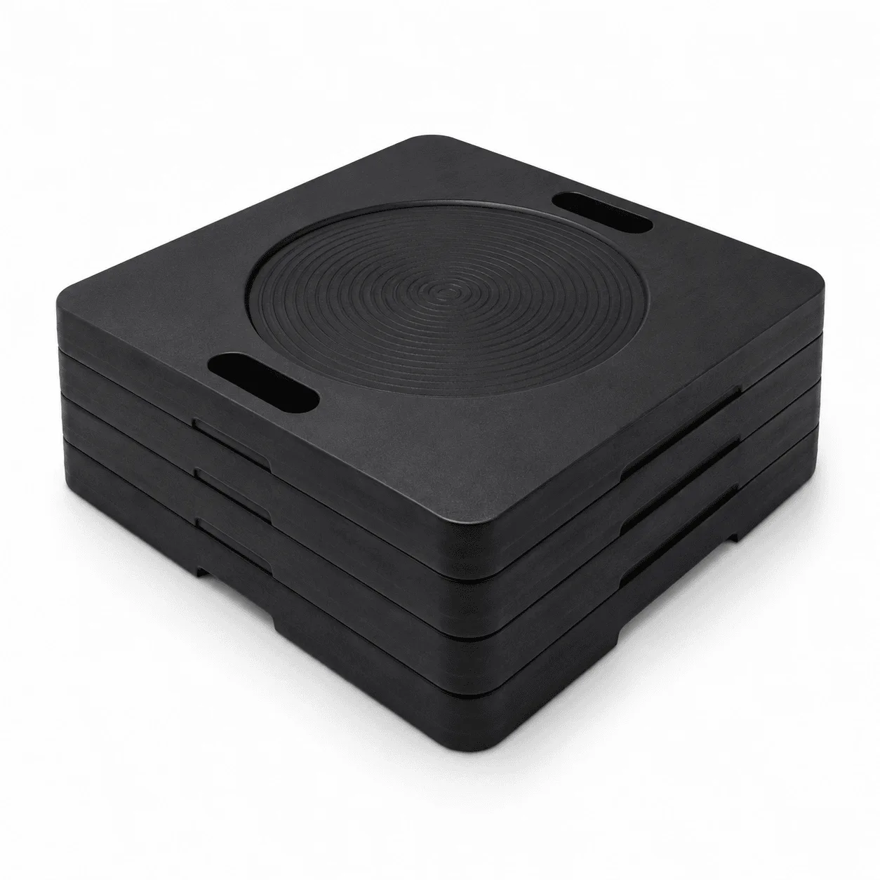
  • Circular recessed support areas
  • Flat support surfaces

This product page is specifically focused on the black pad shown with a strong diagonal groove pattern.

Different surface structures should be selected according to the required equipment contact, handling, support conditions, and product design.

Solid Square Support Structure

The square shape provides a practical combination of support area, stacking efficiency, equipment storage, and repeated positioning.

Square pads can be:

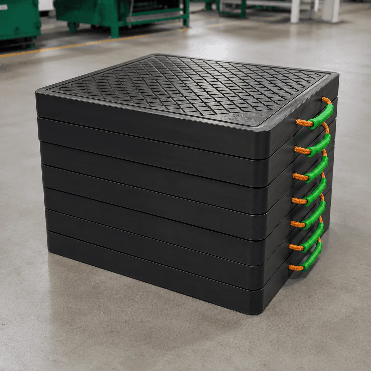
  • Stacked in organized equipment sets
  • Stored inside truck or machinery compartments
  • Positioned using clear straight edges
  • Produced in a wide range of dimensions
  • Used beneath different stabilizer foot shapes

Compared with a round pad of the same maximum outside width, a square pad provides additional geometric area in the corner sections.

A round pad may still be more suitable for other equipment configurations. The correct shape depends on the original stabilizer foot, required effective area, storage arrangement, handling method, and operating conditions.

Rounded Corners and Finished Edges

The pad shown uses rounded outside corners rather than sharp 90-degree projecting corners.

This provides a cleaner panel profile during repeated handling and equipment setup.

Rounded edges can help:

  • Reduce sharp projecting corners
  • Improve the handling profile of the panel
  • Make pads easier to organize during storage
  • Create a cleaner finished product appearance
  • Reduce concentrated corner contact during transportation

The final corner radius should maintain a practical balance between handling and usable support area.

How Grooved Crane Outrigger Pads Distribute Load

An equipment outrigger transfers a concentrated reaction through a relatively small original stabilizer foot.

Grooved Crane Outrigger Pads increase the geometric contact area between the equipment support point and the underlying surface.

The effectiveness of the complete support arrangement depends on:

  • Maximum individual outrigger reaction
  • Pad length and width
  • Pad thickness
  • UHMWPE material structure
  • Original stabilizer foot dimensions
  • Ground bearing condition
  • Position of the applied load
  • Support beneath the complete pad

A larger effective support area can reduce concentrated ground pressure when the pad has sufficient strength and stiffness and receives appropriate support beneath its intended working area.

A large outside dimension alone should not be treated as a universal load-capacity guarantee.

How to Select the Correct Pad Area

The correct pad size should not be selected only according to the total machine weight or rated lifting capacity of a crane.

Individual outriggers can experience different reactions according to the operating configuration.

Important selection factors include:

  • Maximum individual outrigger reaction
  • Allowable ground bearing pressure
  • Original stabilizer foot dimensions
  • Required effective support area
  • Pad material
  • Panel thickness
  • Structural stiffness
  • Boom direction
  • Working radius
  • Load position
  • Outrigger extension
  • Supporting ground condition

A practical starting relationship is:

Maximum Outrigger Reaction ÷ Allowable Ground Bearing Pressure = Required Minimum Support Area

After determining the required area, the material, thickness, stiffness, surface structure, handling requirements, and complete operating condition should also be reviewed.

For additional professional reference, see this external resource about outrigger pad sizing principles.

Why Pad Thickness Matters

Two support pads with identical outside dimensions can behave differently when their thicknesses and material structures are different.

For example, a 600 × 600 mm pad may be supplied in several practical thicknesses:

  • 600 × 600 × 40 mm
  • 600 × 600 × 50 mm
  • 600 × 600 × 60 mm

A larger 1000 × 1000 mm format may use:

  • 1000 × 1000 × 50 mm
  • 1000 × 1000 × 60 mm
  • 1000 × 1000 × 80 mm
  • 1000 × 1000 × 100 mm

Thickness selection should consider:

  • Maximum stabilizer reaction
  • Material stiffness
  • Original equipment foot dimensions
  • Ground condition
  • Required support area
  • Product handling requirements

A thinner panel may be easier to transport, while a thicker pad provides a different structural response. The correct specification depends on the complete equipment support condition.

Why Large Pads Require Additional Consideration

The reference product family includes large pad formats up to approximately 1500 × 1500 mm and 2000 × 2000 mm.

Large-format pads require additional consideration for:

  • Finished product weight
  • Mechanical handling
  • Vehicle transportation
  • Storage space
  • Pad stiffness
  • Equipment reaction
  • Ground support condition

A very large pad should not be selected simply because a larger surface area appears safer.

The support panel still needs sufficient structural performance for the relationship between the equipment foot, applied force, panel thickness, and supporting ground.

Durable UHMWPE Construction

The primary material used for Grooved Crane Outrigger Pads is ultra-high-molecular-weight polyethylene.

UHMWPE provides a practical combination of:

  • Impact resistance
  • Wear resistance
  • Low water absorption
  • Moisture resistance
  • Corrosion-resistant plastic construction
  • Repeated outdoor usability
  • Reusable performance
  • Easy-to-clean surfaces

These material characteristics make the pads suitable for products that are repeatedly transported, positioned, loaded, removed, cleaned, inspected, and stored.

Unlike steel support plates, UHMWPE does not rust.

Compared with traditional timber support products, manufactured plastic pads have low water absorption and do not depend on natural wood grain, knots, or changing moisture content.

Wear Resistance for Repeated Equipment Setup

Outrigger pads may be handled many times during their service life.

Typical repeated-use conditions include:

  • Dragging during positioning
  • Contact with gravel
  • Mud and sand contamination
  • Repeated stabilizer contact
  • Stacking during transportation
  • Outdoor moisture exposure
  • Repeated loading and removal

The wear-resistant characteristics of UHMWPE make the material suitable for repeated equipment support applications when the product is correctly selected and regularly inspected.

The groove surface, lower support face, outside edges, and corners should still be checked before demanding equipment use.

Applications of Grooved Crane Outrigger Pads

Grooved Crane Outrigger Pads can be used with many types of machinery that rely on outriggers or stabilizers during operation.

Typical applications include:

  • Mobile cranes
  • Truck-mounted cranes
  • Knuckle boom cranes
  • Concrete pump trucks
  • Boom trucks
  • Aerial work platforms
  • Digger derricks
  • Utility service vehicles
  • Maintenance trucks
  • Well drilling equipment
  • Forestry machinery
  • Heavy machinery stabilizers
  • Selected industrial lifting equipment

The correct dimensions and thickness should always be matched to the actual equipment and operating conditions.

Mobile Crane Applications

Mobile cranes use outriggers to create a wider operating base during lifting operations.

The reaction acting through each individual support point can change according to:

  • Boom direction
  • Working radius
  • Load position
  • Outrigger extension
  • Crane geometry
  • Operating configuration

When selecting pads for a mobile crane, consider:

  • Maximum individual outrigger reaction
  • Original crane foot dimensions
  • Required support area
  • Supporting ground condition
  • Pad dimensions
  • Pad thickness
  • Material stiffness

The same crane may require different support considerations when operating on concrete, asphalt, gravel, compacted soil, or softer surfaces.

Concrete Pump Truck Applications

Concrete pump trucks also rely on stabilizers to create a wider operating base.

Grooved Crane Outrigger Pads may be used beneath pump truck support legs when the selected size, thickness, material, and complete setup are appropriate.

Important factors include:

  • Maximum stabilizer reaction
  • Boom configuration
  • Working position
  • Original support foot dimensions
  • Ground condition
  • Required support area
  • Pad stiffness

Each support position should be evaluated according to its actual reaction and supporting surface.

Boom Trucks and Utility Equipment

Boom trucks and utility vehicles frequently use stabilizers during lifting, aerial access, maintenance, and material handling operations.

Typical equipment includes:

  • Utility service trucks
  • Digger derricks
  • Aerial work vehicles
  • Truck-mounted lifting equipment
  • Maintenance vehicles
  • Service cranes
  • Forestry vehicles

The required pad specification should be selected according to actual stabilizer reactions and supporting conditions rather than equipment category alone.

Use on Compacted Soil

Compacted soil can vary according to moisture, previous excavation, fill material, and compaction quality.

Before equipment setup, inspect for:

  • Soft areas
  • Loose fill
  • Recent excavation
  • Underground voids
  • Standing water
  • Severe slopes
  • Unstable edges

The effective working area of the pad should receive suitable support underneath.

A larger pad cannot automatically make unsuitable ground safe.

Use on Gravel

Prepared gravel surfaces are common around industrial equipment and temporary operating areas.

Before placing the pad, check:

  • Surface level
  • Compaction
  • Large loose stones
  • Deep depressions
  • Nearby edges
  • Evidence of previous ground movement

Large stones or hard objects directly beneath the pad can create concentrated support points and should be removed before equipment loading.

Use on Asphalt

Asphalt performance can vary according to temperature, pavement thickness, underlying structure, and existing damage.

Consider:

  • High surface temperature
  • Existing cracks
  • Underground structures
  • Drain covers
  • Surface depressions
  • Unsupported pavement edges

A correctly selected support pad increases the effective area, but the underlying pavement still needs to be suitable for the equipment operation.

Use on Concrete

Concrete surfaces should also be evaluated before equipment setup.

Inspect for:

  • Cracks
  • Slab edges
  • Drainage structures
  • Underground voids
  • Damaged sections
  • Changes in surface level

The visible top surface does not always reveal the complete supporting condition beneath the equipment.

Correct Outrigger Positioning

Correct equipment-foot positioning is important when using Grooved Crane Outrigger Pads.

Before loading, check that:

  • The pad is correctly positioned
  • The outrigger foot is within the intended working area
  • The pad is not spanning a large unsupported void
  • The lower surface has suitable support
  • Large objects are not trapped beneath the pad
  • The stabilizer is not unintentionally positioned close to an unsupported edge

A support foot positioned near the intended working area can use the surrounding pad area differently from a foot positioned close to the outer edge.

Four-Pad Equipment Sets

Many cranes, pump trucks, and other outrigger-equipped machines use four stabilizer positions.

A complete set can therefore include four matching pads.

This arrangement can help with:

  • One pad for each equipment support position
  • Consistent panel dimensions around the machine
  • Organized vehicle storage
  • Simplified equipment inventory
  • Easy checking after equipment recovery

Each support position should still be evaluated separately because the individual reaction force and underlying ground condition may differ around the same machine.

Reusable Equipment Support Pads

A major advantage of Grooved Crane Outrigger Pads is their reusable construction.

After equipment operation is completed, the pads can be:

  • Removed from beneath the stabilizers
  • Cleaned
  • Inspected
  • Stacked
  • Returned to equipment storage
  • Transported to another operating location

The square structure makes complete pad sets easier to organize during transportation and storage.

Inspection Before Every Setup

Reusable equipment support pads should be inspected before demanding applications.

Check:

  • Diagonal groove surface
  • Lower support face
  • Rounded edges and corners
  • Visible cracks
  • Severe deformation
  • Deep cuts or gouges
  • Excessive groove damage
  • Other visible structural changes

A damaged pad should be evaluated before returning to heavy equipment support service.

The supporting surface should also be inspected each time the equipment is repositioned.

Cleaning the Grooved Surface

Mud, sand, gravel, oil, and other debris can remain inside the diagonal channels after outdoor operation.

Cleaning can help:

  • Make visual inspection easier
  • Remove debris from the groove pattern
  • Keep the main working surface visible
  • Improve organized storage
  • Prepare the pads for the next equipment setup

Large debris on or beneath the support pad should be removed before equipment loading.

Storage and Transportation

The regular square structure makes the pads suitable for organized storage and transportation.

During storage:

  • Keep complete pad sets together
  • Avoid unstable stacking
  • Separate damaged pads
  • Remove excessive mud and debris
  • Keep groove surfaces accessible for inspection
  • Use suitable handling methods for larger panels

Handling procedures should always match the actual dimensions, thickness, and finished product weight.

Large-format products may require suitable mechanical handling equipment.

Complete Range of Crane Outrigger Pads

You can also view our complete range of crane outrigger pads for mobile cranes, concrete pumps, boom trucks, lifting equipment, stabilizer systems, cribbing support, and related heavy machinery applications.

7 Amazing Powerful Benefits of Grooved Crane Outrigger Pads

  • Deep diagonal groove surface for a distinctive industrial working pattern
  • Durable UHMWPE construction for repeated outdoor equipment setup
  • Wide size range for compact and large equipment support requirements
  • Multiple thickness options for different structural requirements
  • Rounded edges and corners for a clean finished panel profile
  • Low water absorption and corrosion-resistant plastic construction
  • Reusable design for repeated setup, cleaning, inspection, and storage

Why Choose Grooved Crane Outrigger Pads?

Grooved Crane Outrigger Pads provide a practical ground-support solution for mobile cranes, truck-mounted cranes, concrete pump trucks, boom trucks, utility vehicles, and other outrigger-equipped machinery. Their durable UHMWPE construction, deep diagonal surface grooves, square support structure, rounded edges, wide dimensional range, and reusable design make them suitable for many equipment support applications.

Typical reference specifications include approximately 300 × 300 × 20–40 mm, 400 × 400 × 30–50 mm, 500 × 500 × 30–60 mm, 600 × 600 × 40–60 mm, 800 × 800 × 40–80 mm, and 1000 × 1000 × 50–100 mm.

Larger project-specific formats can include approximately 1500 × 1500 × 80–150 mm and 2000 × 2000 × 100–200 mm where the complete equipment, handling, transport, structural, and ground-support requirements are properly evaluated.

Final pad dimensions, thickness, material grade, effective support area, groove structure, edge design, and operating arrangement should always be selected according to the maximum individual outrigger reaction, original stabilizer foot dimensions, supporting ground condition, and actual equipment requirements.

Quality Control

Quality Control and Delivery Standards

Drawing & Material Check

Check drawings for full specifications and confirm materials according to service conditions to prevent product defects.

Machining Quality Control

Inspect all key processing steps and fully verify dimensions, holes, grooves and fitting surfaces.

Finishing & Batch Control

Deburr, chamfer and clean products for easy installation. Ensure uniform quality among batch products.

Packaging & Delivery

Choose appropriate packaging solutions based on product features to protect goods from collision, deformation and mixing during transit.

Processing Quality Control of Engineering Plastics Parts

Unlike metal parts, engineering plastic components still require strict control over dimensions, holes, edges, surface, materials and assembly performance for equipment use.

application

Applications for Engineering Plastic Parts

Engineering plastic parts suit friction, guide, support, buffer, anti-corrosion and insulation areas. We supply UHMWPE, POM, PA, PP/PE components for conveyor, food, mining, machinery, chemical and cable systems, with custom OEM service available.

Our Blog

Latest News & Knowledge

Stay updated with our latest industry insights, company updates and featured articles.

We Love to Hear From You

Need UHMWPE sheets & custom plastic machined/OEM parts?Send specs & material needs, free quote within 24h.