Crane Cribbing Support System is a modular UHMWPE support solution combining bottom pads, stackable cribbing blocks and top support pads for cranes, concrete pumps, outriggers and heavy equipment. The black system uses 610 × 180 × 150 mm blocks with 610 × 610 × 50 mm support pads, while the yellow system uses 600 × 150 × 150 mm blocks with 600 × 600 × 40–60 mm support pads. The reusable cross-stacked structure provides additional equipment setup height and organized multi-layer support.
Crane Cribbing Support System is a modular equipment support solution designed to provide additional height beneath mobile crane outriggers, stabilizers, concrete pump support legs, boom trucks, utility equipment, and other heavy machinery. The complete system can combine a bottom support pad, multiple layers of stackable cribbing blocks, and a top support pad to create an organized equipment support structure.
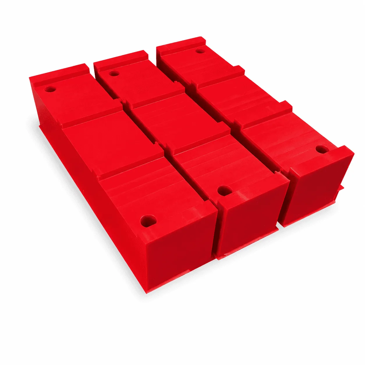
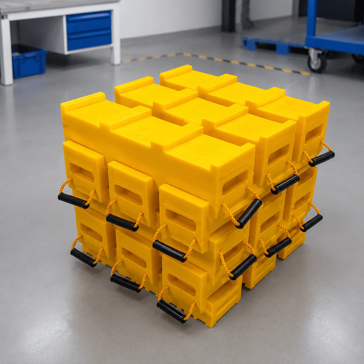
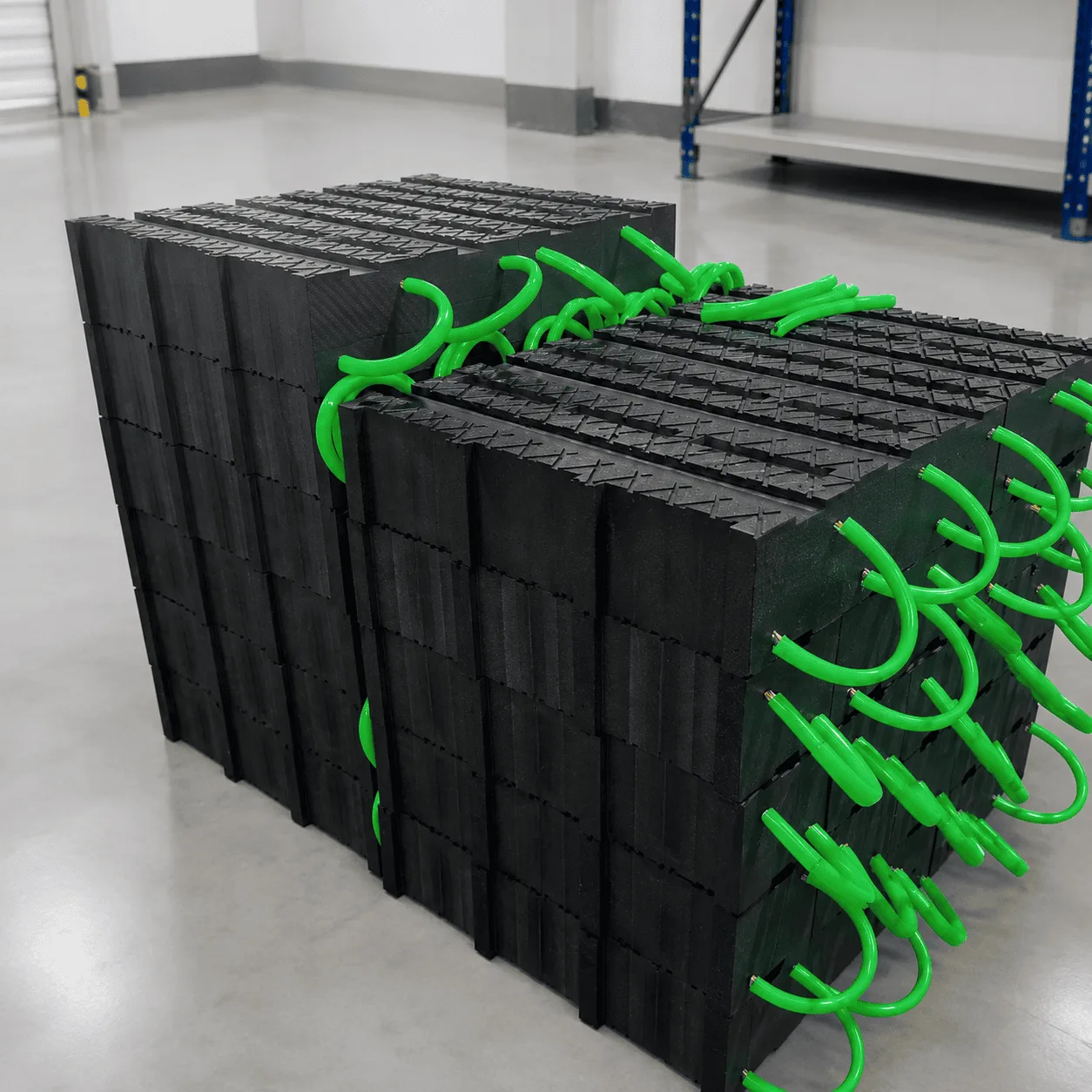
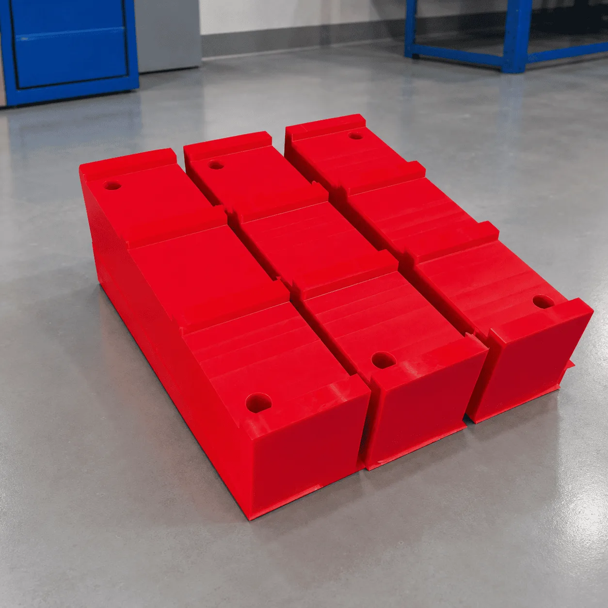
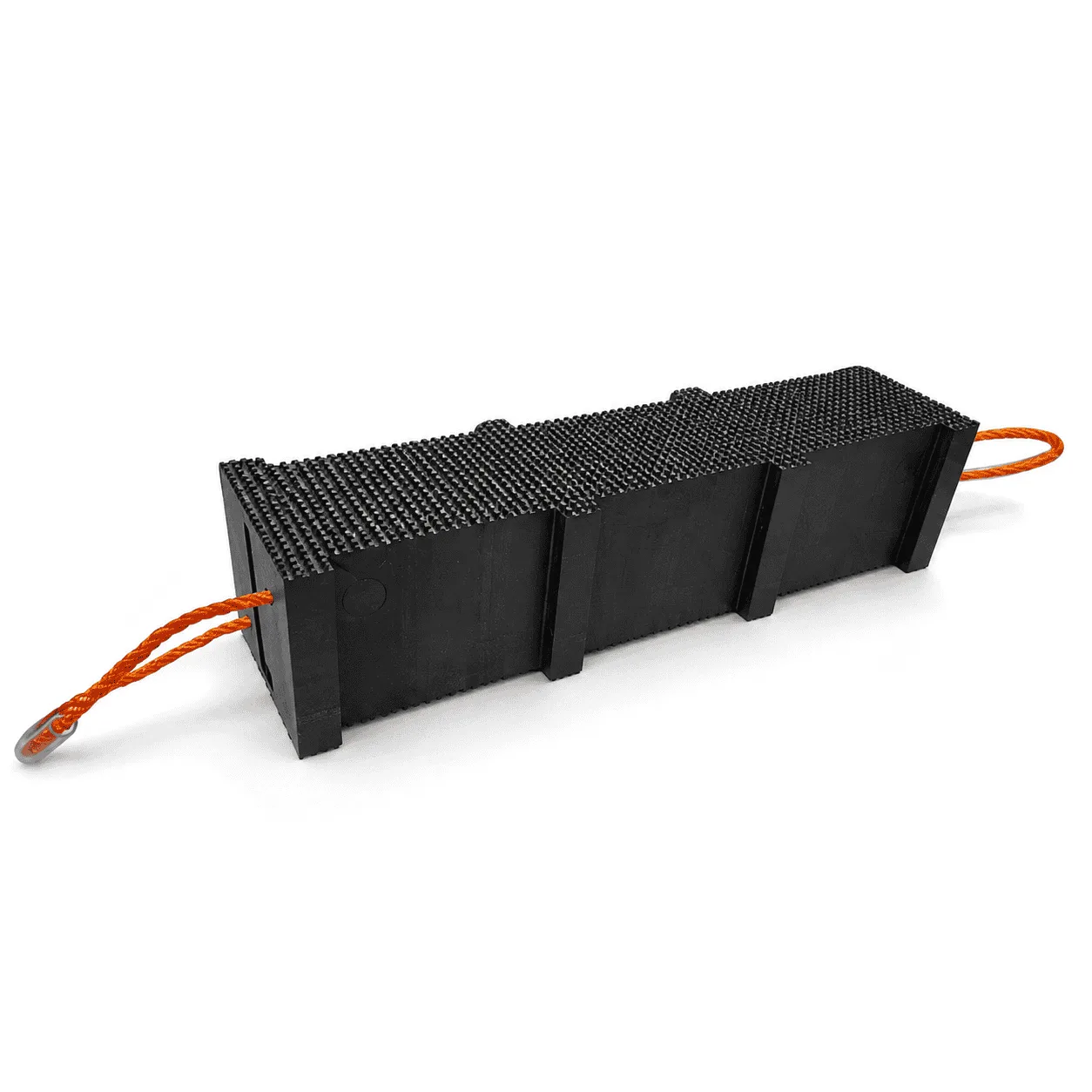
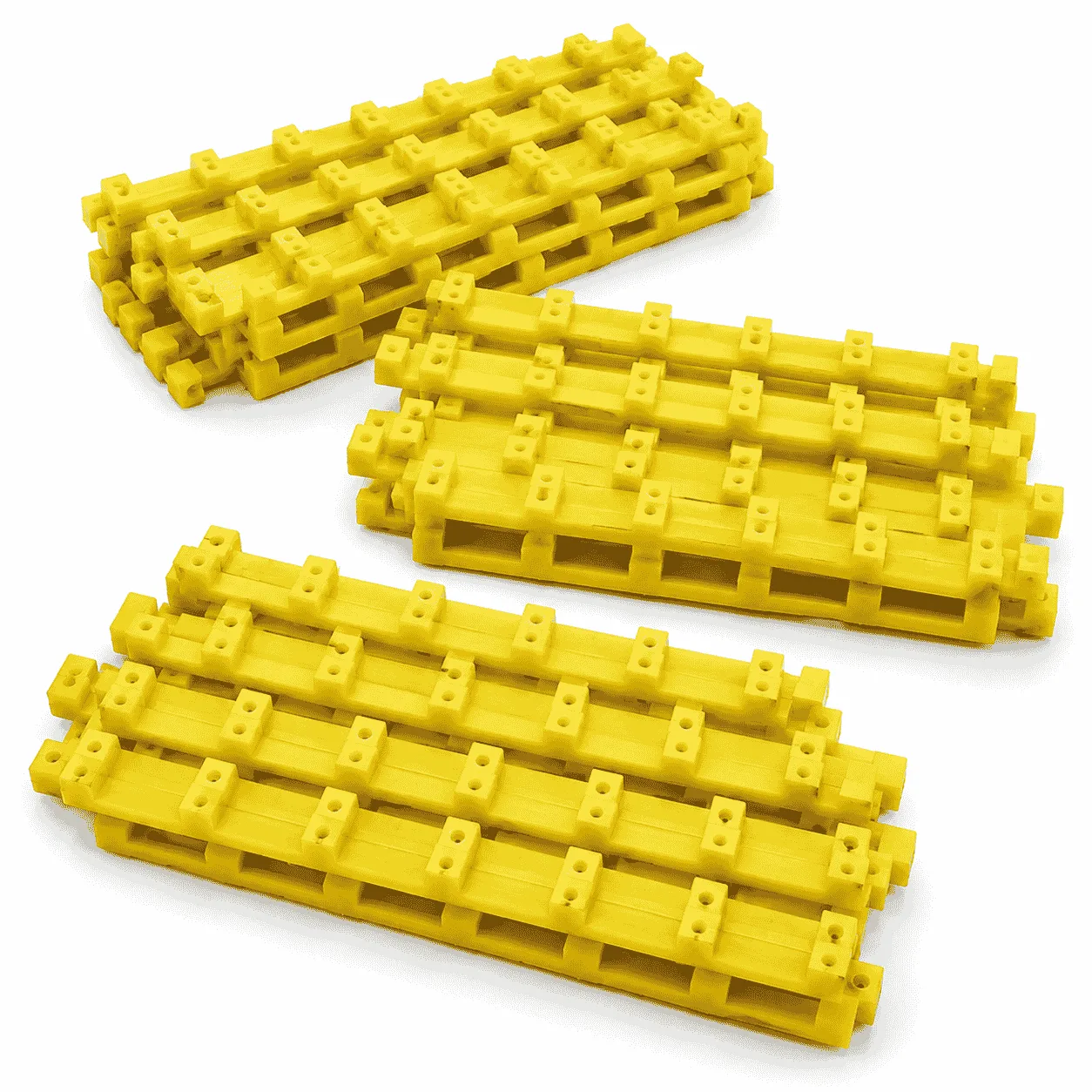
The product system shown is available in both heavy-duty black and high-visibility yellow configurations. The rectangular cribbing blocks feature shaped working surfaces, reinforced structures, and integrated carrying handles. Compatible blocks can be arranged in multiple layers, while the top and bottom support pads create larger contact surfaces at the ends of the cribbing assembly.
Unlike a single outrigger pad, which is mainly used to increase the effective contact area beneath a stabilizer foot, this system is designed to combine ground support with additional equipment setup height. The complete arrangement should be selected according to the equipment reaction, required height, supporting surface, block configuration, and approved operating procedure.
The reference images show two practical Crane Cribbing Support System configurations. Each system uses different block dimensions, weights, and support pad specifications.
| Component | Reference Size | Reference Weight |
|---|---|---|
| Cribbing block | 610 × 180 × 150 mm | Approximately 26 kg |
| Top support pad | 610 × 610 × 50 mm | Approximately 18 kg |
| Bottom support pad | 610 × 610 × 50 mm | Approximately 18 kg |
| Illustrated system footprint | 610 × 610 mm | Depends on final configuration |
| Illustrated overall height | Approximately 701.6 mm | Depends on layer arrangement |
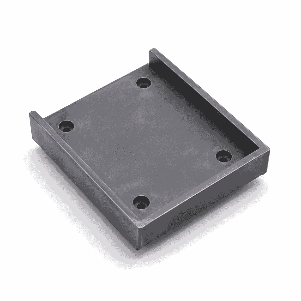
The black system uses large 610 × 180 × 150 mm cribbing blocks with an approximate reference weight of 26 kg per block. The upper and lower support pads measure approximately 610 × 610 × 50 mm and have a reference weight of approximately 18 kg per pad.
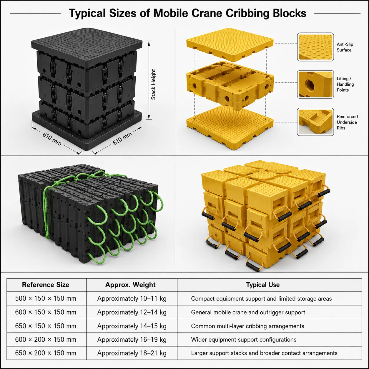
The technical illustration shows a complete assembled footprint of approximately 610 × 610 mm and an illustrated overall height of approximately 701.6 mm. The actual finished support height depends on the number of cribbing layers, block orientation, top and bottom pad thickness, and final system arrangement.
| Component | Reference Size | Reference Weight |
|---|---|---|
| Cribbing block | 600 × 150 × 150 mm | Approximately 10.50 kg |
| Top support pad | 600 × 600 × 40–60 mm | Approximately 14 kg |
| Bottom support pad | 600 × 600 × 40–60 mm | Approximately 14 kg |
The yellow system uses approximately 600 × 150 × 150 mm cribbing blocks with a reference unit weight of approximately 10.50 kg. The top and bottom support pads measure approximately 600 × 600 mm, with thickness options from approximately 40 mm to 60 mm and a reference weight of approximately 14 kg.
This configuration provides a lighter block format for applications where repeated handling, transportation, high visibility, and modular installation are important.
| Specification | Typical Reference |
|---|---|
| Product type | Modular crane cribbing and support system |
| Primary material | UHMWPE |
| Other material option | Selected HDPE structures |
| Block colors | Yellow or black |
| System components | Bottom pad, cribbing blocks and top pad |
| Block arrangement | Multi-layer cross-stacked configuration |
| Surface structure | Interlocking or positioning features |
| Handling feature | Integrated flexible carrying handles |
| Main applications | Mobile cranes, concrete pumps, outriggers and heavy equipment |
Final material, block dimensions, support pad thickness, number of layers, and installation arrangement should be selected according to the actual equipment and operating conditions.
The main advantage of a Crane Cribbing Support System is that the complete arrangement can use three functional sections:
This modular structure allows the support height to be adjusted by changing the number of compatible cribbing layers.
The system should not be assembled by randomly piling individual blocks. Block orientation, working surface contact, supporting ground, top and bottom pad positioning, applied equipment reaction, and total assembly geometry should all be considered.
The bottom pad forms the base of the complete cribbing assembly.
Its main functions include:
The black reference system uses a 610 × 610 × 50 mm bottom support pad, while the yellow reference system uses a 600 × 600 × 40–60 mm support pad.
The base pad should have suitable contact beneath its effective working area. It should not be positioned across large unsupported voids, unstable edges, deep depressions, or loose material without proper evaluation.
The central section of the Crane Cribbing Support System consists of multiple rectangular support blocks.
These blocks create additional height and can be arranged in alternating directions.
The block layers can help provide:
The black system uses 610 × 180 × 150 mm blocks, while the yellow system uses 600 × 150 × 150 mm blocks.
Although both reference systems use a nominal block height of approximately 150 mm, the actual increase in complete equipment support height depends on the orientation and number of layers.
The top support pad creates the upper contact section of the complete system.
Depending on the selected product arrangement, the top pad can provide:
The top pad should be positioned according to the complete support system design and the equipment stabilizer arrangement.
The black reference top pad is approximately 610 × 610 × 50 mm. The yellow reference top pad is approximately 600 × 600 × 40–60 mm.
Rectangular cribbing blocks can be arranged with one layer positioned in one direction and the following layer placed across it.
This cross-stacking arrangement can provide:
For example, one layer may be positioned horizontally while the next layer is placed at approximately 90 degrees.
Additional compatible layers can continue according to the intended support height and system design.
Engineered cribbing systems also use cross-stacked layers, compatible positioning features, and full contact between the primary working surfaces. You can review this external resource about interlocking cribbing system principles.
The reference block designs use raised structural sections that help organize the position of adjoining layers.
Depending on the final product design, these surface features can help:
The interlocking or positioning structure does not replace correct equipment setup.
The complete arrangement still depends on:
Suitable contact between adjoining components is important when building a multi-layer Crane Cribbing Support System.
Before applying equipment load, check that:
Large stones, metal parts, timber fragments, or other objects trapped between working surfaces can create concentrated contact areas and should be removed before loading.
A component that is only partially supported may perform differently from the same product with appropriate support beneath its primary working area.
The black system is the larger and heavier of the two reference configurations.
Its 610 × 180 × 150 mm blocks have an approximate reference weight of 26 kg each.
This format can be considered where:
The reference illustration shows the system assembled to approximately 701.6 mm overall height.
This dimension applies to the illustrated configuration and should not be treated as the only available system height. The final height depends on the number of blocks, layer arrangement, and top and bottom pad configuration.
The yellow system uses a lighter individual block format.
Each reference block measures approximately 600 × 150 × 150 mm and weighs approximately 10.50 kg.
The bright yellow design can help with:
The yellow system also uses flexible carrying handles positioned around the blocks.
Color should not be interpreted as an indication of load capacity. Product suitability depends on the complete material, structure, dimensions, setup, and operating conditions.
The primary material used for the Crane Cribbing Support System is UHMWPE.
Typical material characteristics include:
These characteristics make the system suitable for repeated transportation, installation, removal, cleaning, inspection, and storage.
Unlike steel support components, polyethylene does not rust. Compared with traditional timber cribbing, manufactured plastic components do not depend on natural wood grain, knots, or changing moisture content.
The reference blocks include flexible carrying handles positioned around the sides.
These provide defined handling points when components need to be:
The number and position of handles depend on the block design.
Before lifting, inspect:
Handling procedures should always match the actual component weight.
Crane Cribbing Support System can be used for a range of temporary equipment support and additional-height applications.
Typical equipment includes:
The complete system configuration should always be selected according to the actual equipment, applied forces, required height, supporting surface, and operating procedure.
Mobile crane outriggers may require additional support height depending on equipment geometry and operating conditions.
Important factors include:
The support system should not be selected only according to the total crane weight.
Individual outrigger reactions can change according to boom position, working radius, load location, outrigger extension, and equipment configuration.
Concrete pump trucks may also require additional height beneath stabilizer systems in selected operating conditions.
The complete system can combine:
The exact arrangement depends on the stabilizer reaction, required height, equipment design, ground condition, and approved setup procedure.
A single outrigger pad and a complete cribbing support system perform different primary functions.
An outrigger pad is mainly used to increase the effective contact area between the equipment and supporting ground.
A cribbing system is mainly used to create additional support height through a structured multi-layer arrangement.
A complete equipment support configuration may include both product types.
You can also view our complete range of crane outrigger pads for mobile cranes, concrete pumps, lifting equipment, stabilizer systems, and related heavy machinery support applications.
A major advantage of a modular Crane Cribbing Support System is the ability to create different support heights by changing the number of layers.
Both reference block systems use a nominal block height of approximately 150 mm.
Additional layers increase the overall assembly height, but increasing height also changes:
A taller support system should not be created simply because additional blocks are available.
The suitability of a support system cannot be determined from one universal equipment tonnage number.
Important factors include:
A properly supported component can perform differently from the same product placed across a void, on an unstable edge, or with only partial surface contact.
Additional support height may be required where equipment geometry or surrounding surface levels prevent the stabilizer from reaching the intended support position.
Before installation, inspect the area for:
The bottom support pad should have appropriate contact beneath its effective working area.
Very weak, severely uneven, or unsupported ground may require additional preparation or another engineered support solution.
A major advantage of the Crane Cribbing Support System is its reusable modular construction.
After equipment operation is completed, the components can be:
The consistent block and pad dimensions make complete sets easier to organize during storage and transportation.
Reusable support components should be inspected before demanding applications.
Check:
A damaged component should be evaluated before returning to heavy equipment support service.
Mud, sand, gravel, and other debris can remain on the components after outdoor operations.
Cleaning can help:
During storage:
Crane Cribbing Support System provides a modular support solution where cranes, concrete pumps, boom trucks, outriggers, and other heavy equipment require additional setup height. The combination of bottom support pads, stackable cribbing layers, top support pads, durable UHMWPE material, positioning structures, and integrated handles creates a practical system for repeated equipment support applications.
The black reference system uses 610 × 180 × 150 mm blocks weighing approximately 26 kg each, combined with 610 × 610 × 50 mm top and bottom support pads weighing approximately 18 kg each. The illustrated system has a 610 × 610 mm footprint and an overall height of approximately 701.6 mm.
The yellow reference system uses 600 × 150 × 150 mm blocks weighing approximately 10.50 kg each, combined with 600 × 600 × 40–60 mm top and bottom support pads with a reference weight of approximately 14 kg.
Final system dimensions, number of layers, material grade, block arrangement, top and bottom pad thickness, support footprint, and installation configuration should always be selected according to the actual equipment, stabilizer reaction, required height, supporting ground, and operating requirements.
Check drawings for full specifications and confirm materials according to service conditions to prevent product defects.
Inspect all key processing steps and fully verify dimensions, holes, grooves and fitting surfaces.
Deburr, chamfer and clean products for easy installation. Ensure uniform quality among batch products.
Choose appropriate packaging solutions based on product features to protect goods from collision, deformation and mixing during transit.
Unlike metal parts, engineering plastic components still require strict control over dimensions, holes, edges, surface, materials and assembly performance for equipment use.
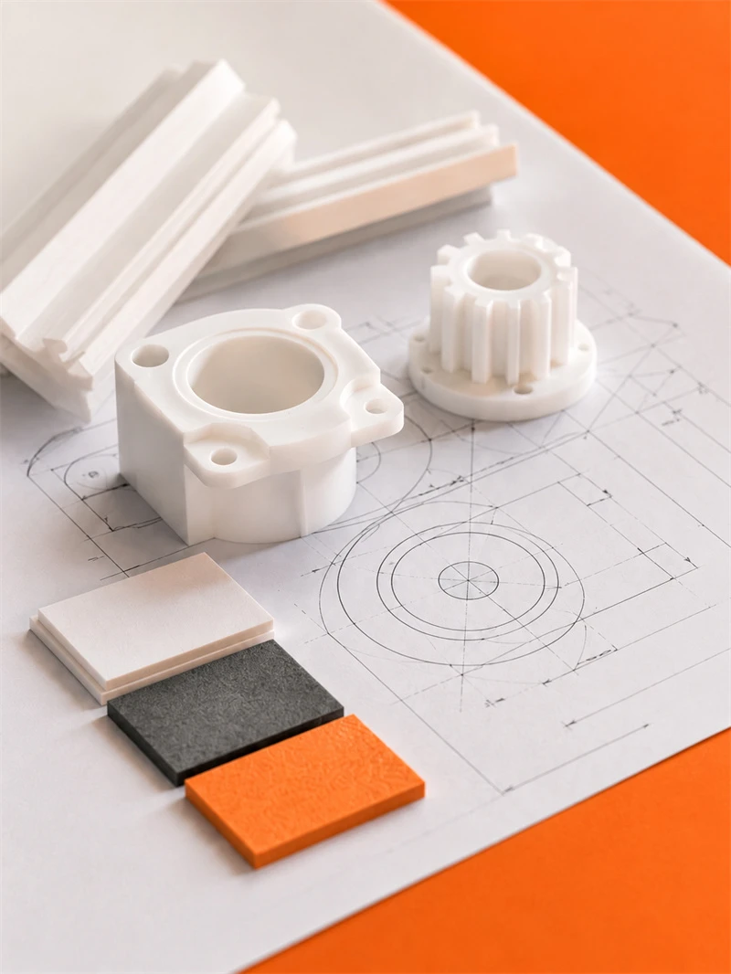
Engineering plastic parts suit friction, guide, support, buffer, anti-corrosion and insulation areas. We supply UHMWPE, POM, PA, PP/PE components for conveyor, food, mining, machinery, chemical and cable systems, with custom OEM service available.
Stay updated with our latest industry insights, company updates and featured articles.

Engineering plastics are increasingly used in industrial machinery, automated production lines, conveyor systems, packaging equipment, and food-processing machines. Materials such as nylon, UHMWPE, POM, and

Both are lightweight, corrosion-resistant, wear-resistant, and suitable for CNC machining. However, they perform very differently

Wear is a common cause of failure in conveyor systems, packaging machinery, automated equipment, mining

CNC machining is widely used to produce plastic prototypes, low-volume parts, replacement components, jigs, fixtures,

Both are lightweight, corrosion-resistant, wear-resistant, and suitable for CNC machining. However, they perform very differently

Wear is a common cause of failure in conveyor systems, packaging machinery, automated equipment, mining

CNC machining is widely used to produce plastic prototypes, low-volume parts, replacement components, jigs, fixtures,
Need UHMWPE sheets & custom plastic machined/OEM parts?Send specs & material needs, free quote within 24h.