Heavy Duty UHMWPE Recessed Crane Outrigger Pads

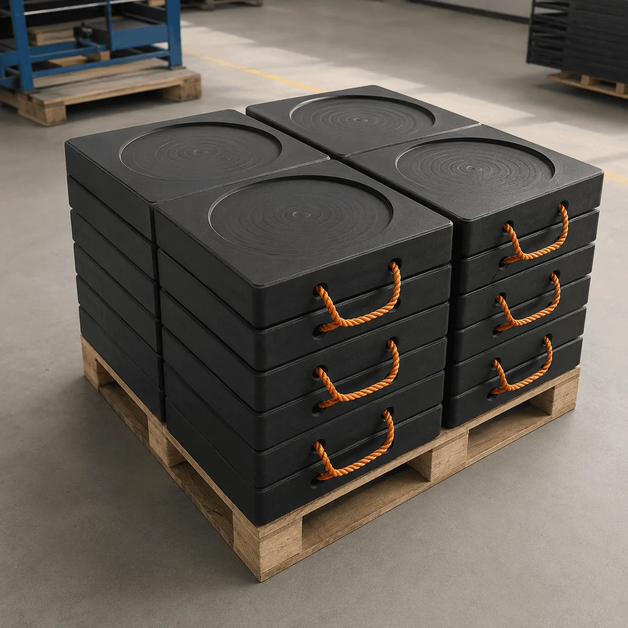
Recessed Crane Outrigger Pads are reusable UHMWPE support panels featuring solid square structures, central circular positioning recesses and multiple carrying handles. Practical reference sizes include 600 × 600 × 50–60 mm, 800 × 800 × 60–80 mm and 1000 × 1000 × 80–100 mm for mobile cranes, concrete pumps, boom trucks and other stabilizer-equipped machinery.

category Brand:
Share :

Description

Product Description

Recessed Crane Outrigger Pads

Recessed Crane Outrigger Pads are heavy-duty UHMWPE support panels designed for mobile crane outriggers, concrete pump stabilizers, boom truck support legs, truck-mounted cranes, aerial work platforms and other machinery that uses hydraulic support legs during operation.

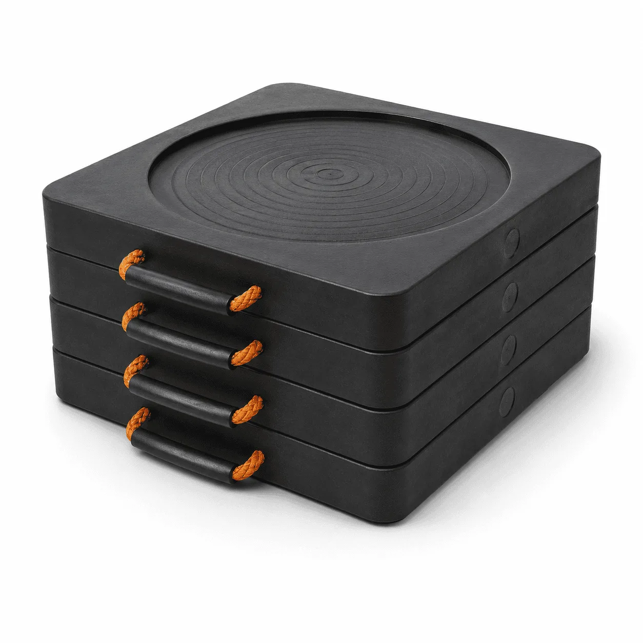
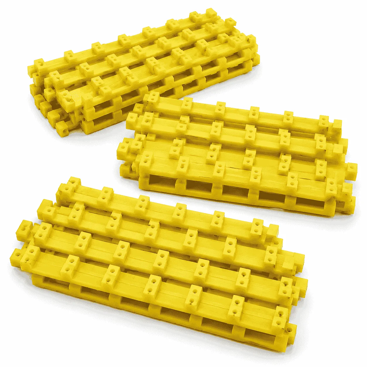
The product shown features a solid square panel structure, a circular recessed positioning area in the centre of the upper working surface and multiple high-visibility carrying handles around the panel edges. Matching pads can be stacked together as a complete equipment support set for transportation, storage and repeated use.

The central circular recess provides a clearly defined positioning area for a compatible crane or machinery stabilizer foot. This structure distinguishes the product from completely smooth, rough-surface, cross-ribbed and deeply grooved support pads.

The recess diameter and depth should be selected according to the actual equipment-foot dimensions. One fixed recess size should not be assumed to fit every mobile crane, concrete pump or boom truck.

Reference Sizes of Recessed Crane Outrigger Pads

The precise dimensions of the pads shown cannot be confirmed from the product image alone. The following specifications are practical reference sizes for this type of solid UHMWPE crane support pad.

Reference Pad SizePractical Recess RangeTypical Application
500 × 500 × 50 mmØ200–250 mmCompact stabilizers and smaller mobile equipment
600 × 600 × 50 mmØ250–300 mmGeneral boom trucks and truck-mounted cranes
600 × 600 × 60 mmØ250–320 mmThicker general-purpose crane support
700 × 700 × 60 mmØ300–350 mmMedium stabilizer support requirements
800 × 800 × 60 mmØ350–400 mmConcrete pumps and medium heavy equipment
800 × 800 × 80 mmØ350–420 mmThicker pump truck and crane support
900 × 900 × 80 mmØ400–450 mmLarger crane and pump truck stabilizers
1000 × 1000 × 80 mmØ450–500 mmLarge mobile equipment support
1000 × 1000 × 100 mmØ450–520 mmLarge heavy-equipment stabilizers
1200 × 1200 × 100 mmØ500–600 mmLarge-format equipment support applications

The approximately 500 × 500 × 50 mm and 600 × 600 × 50–60 mm formats provide relatively compact options where equipment storage and repeated handling are important.

The approximately 700 × 700 × 60 mm and 800 × 800 × 60–80 mm formats provide broader geometric support areas for medium-size cranes, concrete pumps and boom truck stabilizers.

Larger products such as approximately 900 × 900 × 80 mm, 1000 × 1000 × 80–100 mm and 1200 × 1200 × 100 mm require additional consideration for finished weight, transportation, vehicle storage and handling methods.

The recess dimensions shown above are practical reference ranges rather than fixed production standards. The final recess diameter should provide appropriate clearance around the actual stabilizer foot without removing excessive material from the primary support section.

A practical recess depth may range from approximately 5 mm to 15 mm, depending on the total pad thickness, equipment-foot geometry and required remaining material thickness.

Final dimensions, thickness and recess geometry should always be selected according to the maximum individual stabilizer reaction, original equipment-foot dimensions, required support area, UHMWPE stiffness and supporting surface condition.

Main Product Specifications

SpecificationTypical Reference
Product typeRecessed crane and heavy-equipment outrigger support pad
Primary materialUHMWPE
Main panel shapeSquare
Positioning structureCentral circular recess
Reference colorBlack
Other practical colorsYellow, red, blue, green and equipment-identification colors
Reference thickness rangeApproximately 50–100 mm
Practical recess depthApproximately 5–15 mm according to pad thickness
Handling featuresMultiple flexible carrying handles
Storage structureStackable matching support-pad sets
Main applicationsMobile cranes, concrete pumps, boom trucks and heavy equipment

Final material grade, pad dimensions, panel thickness, recess diameter, recess depth, surface finish, handle arrangement and outside shape should be matched to the actual equipment and operating requirements.

Central Circular Recess Design

The defining feature of Recessed Crane Outrigger Pads is the circular positioning recess located near the centre of the upper working surface.

The recessed area can provide:

  • A clearly visible stabilizer-foot positioning area
  • A repeatable reference point during equipment setup
  • Easy identification of the intended upper working face
  • A defined contact area for compatible circular stabilizer feet
  • Visual confirmation that the equipment foot is positioned away from the panel edge

The recess should not be described as a universal locking mechanism. Its function depends on the relationship between the recess diameter, recess depth, stabilizer-foot dimensions and equipment position.

If the recess is too small, the original equipment foot may not sit correctly. If the recess is unnecessarily large or deep, too much material may be removed from the main support section.

How to Select the Recess Diameter

The circular recess should be designed using the actual stabilizer-foot measurements rather than the total size or weight of the machine.

Important measurements include:

  • Outside diameter of the stabilizer foot
  • Shape of the lower equipment-foot surface
  • Required positioning clearance
  • Expected foot movement during equipment setup
  • Total pad thickness
  • Required remaining material beneath the recess

For example, an equipment foot measuring approximately Ø280 mm may require a recess slightly larger than the original foot diameter to allow practical positioning. The final clearance should be confirmed from the equipment dimensions and production drawing.

The circular positioning area should normally remain close to the intended centre of the support panel unless the equipment structure requires another approved position.

Why Recess Depth Matters

The depth of the circular recess affects the remaining thickness of the UHMWPE directly beneath the stabilizer foot.

A shallow recess can provide a visible positioning reference while retaining most of the original panel thickness.

A deeper recess creates a more pronounced positioning area but removes more material from the main support section.

Recess depth should therefore consider:

  • Total panel thickness
  • Required remaining UHMWPE thickness
  • Stabilizer-foot geometry
  • Maximum individual equipment reaction
  • Material grade and stiffness
  • Supporting surface condition

The deepest possible recess is not automatically the best option. The structure should provide sufficient positioning guidance while maintaining an appropriate solid support section.

Solid Square Support Structure

The product combines its circular recess with a solid square UHMWPE outside structure.

A square support panel provides:

  • Efficient use of the available geometric support area
  • Straight edges for positioning and stacking
  • Compatibility with circular and rectangular equipment feet
  • Multiple practical length, width and thickness combinations
  • Organized vehicle and warehouse storage

The stabilizer foot should remain within the intended recessed working area. The support pad should not span a large unsupported void or be positioned close to an unstable edge.

Multiple Carrying Handles

The reference product uses multiple flexible carrying handles around the pad edges.

The handles provide several gripping positions when the panels need to be:

  • Removed from vehicle or warehouse storage
  • Moved toward individual stabilizer positions
  • Positioned before equipment setup
  • Adjusted before loading
  • Recovered after operation
  • Stacked with matching pads
  • Returned to the transport vehicle

Multiple handles can be especially useful for larger panels because they allow coordinated team handling.

The presence of handles does not mean every pad can safely be lifted by one person. Large-format panels may require suitable mechanical handling equipment.

Before moving a pad, inspect:

  • The flexible handle material
  • The protective grip sections
  • The handle attachment points
  • The surrounding UHMWPE structure
  • Visible cuts, looseness or excessive wear

The handles are intended for transportation and positioning. They are not structural components supporting the equipment load.

Stackable Equipment Support Sets

The product image shows several matching Recessed Crane Outrigger Pads stacked together.

A stackable design can help with:

  • Keeping complete crane or pump-truck pad sets together
  • Organizing vehicle and warehouse storage
  • Separating different pad dimensions and recess sizes
  • Checking product quantities before equipment setup
  • Confirming that all pads have been recovered after operation
  • Preparing matching support pads for the next location

The storage surface should be reasonably level and suitable for the combined weight of the complete stack.

UHMWPE Material Construction

The primary material used for Recessed Crane Outrigger Pads is ultra-high-molecular-weight polyethylene, commonly abbreviated as UHMWPE.

UHMWPE is a thermoplastic polyethylene with extremely long molecular chains. It is associated with high toughness, impact strength, extremely low moisture absorption, low friction and strong abrasion resistance.

For a general material explanation, see the Wikipedia article about ultra-high-molecular-weight polyethylene.

Practical material characteristics for reusable crane support pads include:

  • High impact resistance
  • Strong abrasion resistance
  • Extremely low moisture absorption
  • Resistance to many acids and alkalis
  • Resistance to many corrosive chemicals
  • Corrosion-resistant plastic construction
  • Reusable industrial performance
  • Easy-to-clean working surfaces

Chemical resistance should not be interpreted as universal resistance to every substance. Compatibility depends on the exact chemical, concentration, temperature, exposure time and selected UHMWPE grade.

How Recessed Crane Outrigger Pads Work

A crane or heavy-equipment stabilizer transfers a concentrated reaction through its original equipment foot.

Recessed Crane Outrigger Pads create a larger geometric support area beneath that foot while providing a visible central positioning section.

The performance of the complete support arrangement depends on:

  • Maximum individual stabilizer reaction
  • Panel length and width
  • Panel thickness
  • Recess diameter and depth
  • Remaining material thickness beneath the recess
  • UHMWPE grade and stiffness
  • Original equipment-foot dimensions
  • Supporting surface condition
  • Support beneath the complete panel area

A larger outside dimension provides a larger geometric footprint, but panel dimensions alone should not be treated as a universal safe-working-load rating.

How to Select the Correct Pad Size

The correct support pad should not be selected only according to total crane weight or maximum rated lifting capacity.

Individual outrigger reactions can change according to:

  • Boom direction
  • Working radius
  • Lifted load
  • Outrigger extension
  • Equipment geometry
  • Operating configuration

Important selection factors include:

  • Maximum reaction at one stabilizer
  • Original equipment-foot diameter
  • Required effective support area
  • Supporting ground condition
  • Panel dimensions
  • Panel thickness
  • Recess geometry
  • Material stiffness
  • Handling and storage requirements

Each support position should be evaluated separately because equipment reactions and ground conditions can differ around the same machine.

Applications of Recessed Crane Outrigger Pads

Recessed Crane Outrigger Pads can be used with stabilizer-equipped machinery that has compatible circular or near-circular support feet.

  • Mobile cranes
  • Truck-mounted cranes
  • Knuckle boom cranes
  • Boom trucks
  • Concrete pump trucks
  • Boom pumps
  • Aerial work platforms
  • Digger derricks
  • Utility service vehicles
  • Maintenance trucks
  • Tree-care equipment
  • Heavy machinery stabilizers
  • Selected industrial lifting equipment

The recess diameter, panel dimensions and thickness should always be matched to the actual equipment foot and support requirements.

Mobile Crane Applications

Mobile crane outrigger reactions can vary according to boom direction, working radius, lifted load, crane geometry and outrigger extension.

Before selecting a support pad, consider:

  • Maximum individual outrigger reaction
  • Original crane-foot diameter
  • Required support area
  • Ground condition
  • Panel dimensions and thickness
  • Recess diameter and depth
  • Remaining material below the recess

The same crane may require different support considerations at different positions or operating configurations.

Concrete Pump and Boom Truck Applications

Concrete pumps and boom trucks also use hydraulic stabilizers to create a wider operating base.

Important selection factors include:

  • Maximum stabilizer reaction
  • Boom position and configuration
  • Original support-foot dimensions
  • Required support area
  • Supporting surface condition
  • Pad dimensions and recess geometry

Each stabilizer location should be checked independently because reactions and ground conditions can differ around the same vehicle.

Correct Stabilizer-Foot Positioning

Correct positioning is particularly important when using a recessed support panel.

Before applying equipment load, confirm that:

  • The support pad is correctly positioned
  • The stabilizer foot fits inside the intended circular recess
  • The foot is not resting on the outer recess edge
  • The panel is not spanning a large unsupported void
  • The lower surface has suitable support
  • Large hard objects are not trapped beneath the panel
  • The equipment support point is not close to an unstable edge

The recessed working area should remain free from excessive mud, oil, stones and metal debris.

Inspection, Cleaning and Storage

Reusable support pads should be inspected before each demanding equipment setup.

Check:

  • The upper working surface
  • The circular recess and its outside edge
  • The lower support surface
  • The outside panel edges and corners
  • The carrying handles
  • The handle attachment points
  • Visible cracks or severe deformation
  • Deep cuts or excessive wear

After operation, remove mud, sand, oil, gravel and other debris from the primary working surfaces.

During storage:

  • Keep matching pad sizes and recess diameters together
  • Avoid unstable stacking
  • Separate damaged products
  • Inspect handles before moving pads
  • Use appropriate handling methods for large panels
  • Keep recessed surfaces accessible for inspection

Related Crane Outrigger Pads

You can also view our complete range of crane outrigger pads for mobile cranes, concrete pumps, boom trucks, hydraulic stabilizer systems, cribbing products and other heavy machinery applications.

7 Amazing Powerful Benefits of Recessed Crane Outrigger Pads

  • Central circular recess provides a defined stabilizer-foot positioning area
  • Recess diameter and depth can be matched to compatible equipment feet
  • Solid UHMWPE construction for demanding industrial applications
  • High impact and abrasion resistance for repeated equipment setup
  • Multiple carrying handles for positioning and coordinated handling
  • Stackable square panels for organized transportation and storage
  • Reusable design for repeated cleaning, inspection and relocation

Why Choose Recessed Crane Outrigger Pads?

Recessed Crane Outrigger Pads provide a practical support solution for mobile cranes, truck-mounted cranes, boom trucks, concrete pumps and other stabilizer-equipped machinery with compatible circular support feet.

The product combines a solid square UHMWPE structure, a central circular positioning recess and multiple carrying handles.

Typical reference specifications include approximately 500 × 500 × 50 mm, 600 × 600 × 50–60 mm, 800 × 800 × 60–80 mm, 900 × 900 × 80 mm and 1000 × 1000 × 80–100 mm.

Final pad dimensions, thickness, recess diameter, recess depth, remaining material thickness, UHMWPE grade and handle arrangement should always be selected according to the maximum individual stabilizer reaction, original equipment-foot dimensions, supporting surface condition and actual operating requirements.

Quality Control

Quality Control and Delivery Standards

Drawing & Material Check

Check drawings for full specifications and confirm materials according to service conditions to prevent product defects.

Machining Quality Control

Inspect all key processing steps and fully verify dimensions, holes, grooves and fitting surfaces.

Finishing & Batch Control

Deburr, chamfer and clean products for easy installation. Ensure uniform quality among batch products.

Packaging & Delivery

Choose appropriate packaging solutions based on product features to protect goods from collision, deformation and mixing during transit.

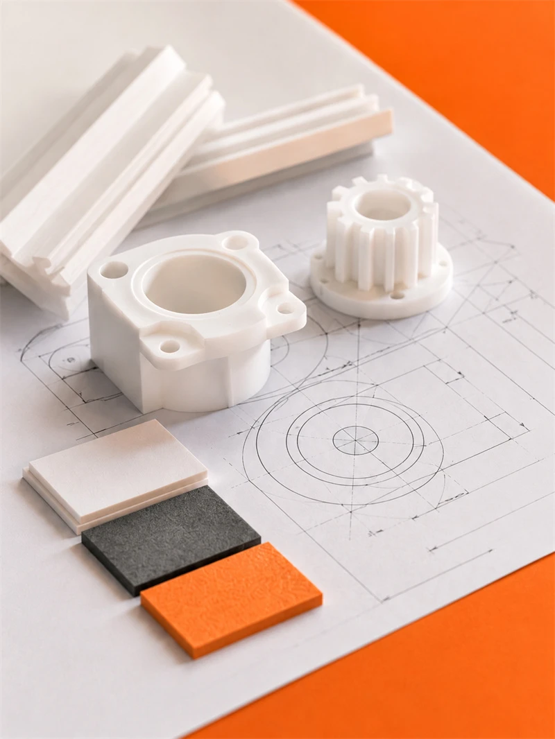
Processing Quality Control of Engineering Plastics Parts

Unlike metal parts, engineering plastic components still require strict control over dimensions, holes, edges, surface, materials and assembly performance for equipment use.

application

Applications for Engineering Plastic Parts

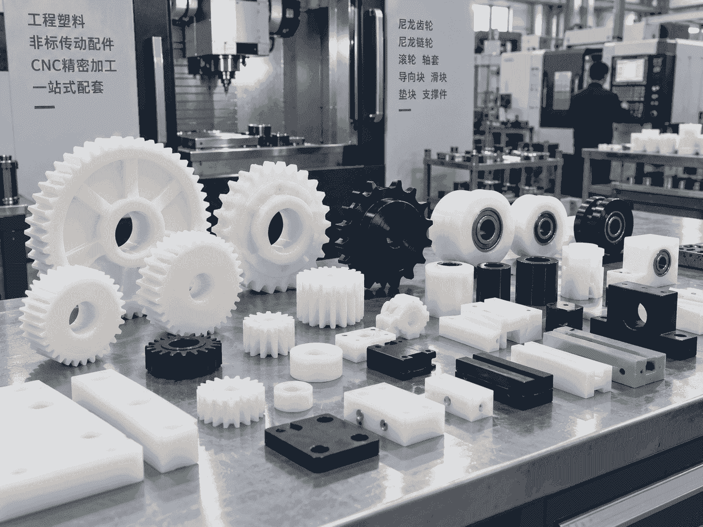
Engineering plastic parts suit friction, guide, support, buffer, anti-corrosion and insulation areas. We supply UHMWPE, POM, PA, PP/PE components for conveyor, food, mining, machinery, chemical and cable systems, with custom OEM service available.

Our Blog

Latest News & Knowledge

Stay updated with our latest industry insights, company updates and featured articles.

We Love to Hear From You

Need UHMWPE sheets & custom plastic machined/OEM parts?Send specs & material needs, free quote within 24h.