Wear Resistant HDPE Crane Foot Support Pads

Crane Foot Support Pads are durable polyethylene support panels designed to distribute stabilizer and outrigger forces over a larger ground area. Typical reference sizes include 450 × 450 × 25 mm, 600 × 600 × 40 mm, 800 × 800 × 40–60 mm and 1000 × 1000 × 50–80 mm. The square structure, circular recessed positioning area, reinforced design and reusable construction make the pads suitable for mobile cranes, pump trucks, boom trucks and other stabilizer-equipped machinery.

category Brand:
Share :

Description

Product Description

Crane Foot Support Pads

Crane Foot Support Pads are durable polyethylene support panels designed to create a larger effective contact area beneath crane outriggers, stabilizer feet, concrete pump supports, boom truck legs, and other outrigger-equipped machinery. The pads help distribute concentrated equipment reactions across a broader supporting surface when the correct size, thickness, material structure, and installation method are selected.

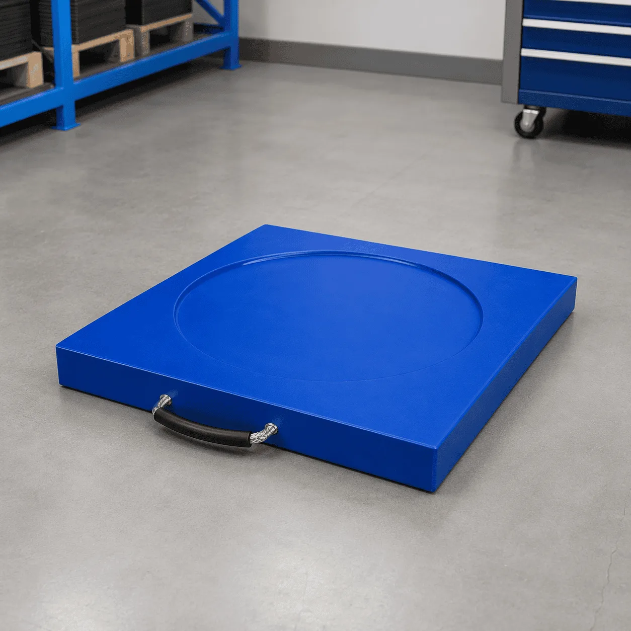
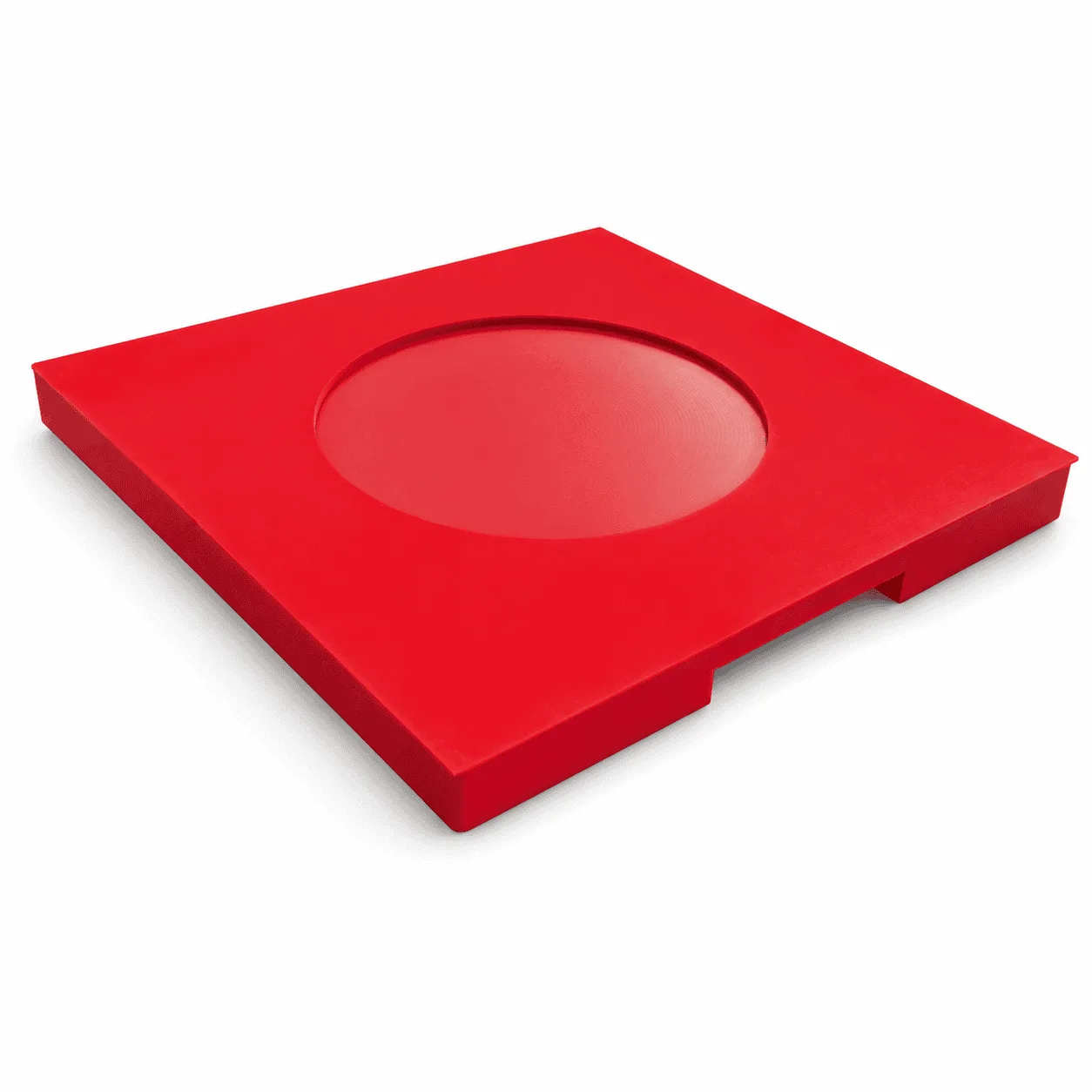
The product shown features a square red panel, a large circular recessed support area in the center, a solid upper working surface, and a reinforced lower structure. The recessed area provides a clear positioning zone for the stabilizer foot, while the square outer dimensions create a practical support footprint beneath the equipment.

Unlike temporary roadway mats, which are designed to create continuous access routes for vehicles, these support pads are placed directly beneath individual equipment feet. Their primary function is to increase the effective bearing area between the stabilizer and the supporting ground.

Typical Sizes of Crane Foot Support Pads

Crane Foot Support Pads can be supplied in different square dimensions and thicknesses according to the equipment type, maximum outrigger reaction, stabilizer foot size, supporting ground condition, and required effective bearing area.

Typical reference specifications include:

Reference Size Typical Thickness Approx. Weight Typical Application
450 × 450 mm 25 mm Approximately 5 kg Small stabilizers and lighter equipment
600 × 600 mm 40 mm Approximately 14–15 kg General truck and equipment outriggers
700 × 700 mm 40–50 mm Approximately 19–24 kg Medium crane and stabilizer support
800 × 800 mm 40–60 mm Approximately 25–38 kg Larger vehicle and crane support areas
900 × 900 mm 50–60 mm Approximately 38–48 kg Heavy equipment support applications
1000 × 1000 mm 50–80 mm Approximately 48–78 kg Large stabilizer reactions and wider support areas

Other practical thickness options may include approximately 25 mm, 30 mm, 40 mm, 50 mm, 60 mm, 70 mm, and 80 mm. The final thickness should not be selected by equipment weight alone.

Actual product weight can vary according to exact dimensions, material density, circular recessed area, lower reinforcement structure, carrying features, edge design, and other structural details.

Main Product Specifications

Specification Typical Reference
Product type Crane and equipment foot support pad
Primary material HDPE or selected high-performance polyethylene grade
Common shape Square
Common color Red
Other color options Black, blue, yellow and other project-specific colors
Upper structure Circular recessed positioning area
Lower structure Flat or reinforced support structure depending on design
Typical use Crane outriggers, stabilizers and machinery support feet

The final material, dimensions, thickness, reinforcement structure, and center recess should be selected according to the actual equipment and support conditions.

How to Select the Correct Support Pad Area

The correct pad size should not be selected only according to the total weight or rated lifting capacity of the machine.

A crane, concrete pump, or boom truck can transfer different forces through individual stabilizers depending on the operating configuration.

Important selection factors include:

  • Maximum outrigger reaction force
  • Allowable ground bearing pressure
  • Original stabilizer foot dimensions
  • Required effective support area
  • Pad material
  • Pad thickness
  • Structural rigidity
  • Ground condition
  • Boom direction
  • Working radius
  • Equipment configuration
  • Ground slope

A practical starting relationship is:

Maximum Outrigger Reaction Force ÷ Allowable Ground Bearing Pressure = Minimum Effective Pad Area

After determining the required minimum area, the strength and stiffness of the support pad should also be evaluated.

For additional technical information, see this external resource about outrigger pad sizing principles.

Why Pad Rigidity Also Matters

A support pad does not automatically distribute the outrigger reaction uniformly across its complete geometric area.

The actual load distribution depends on the relationship between:

  • Pad stiffness
  • Pad thickness
  • Material structure
  • Stabilizer foot size
  • Load position
  • Ground stiffness
  • Support beneath the pad

If the support pad is not sufficiently rigid for the application, a smaller part of the pad may carry a greater proportion of the force.

For demanding applications, simply increasing the outside dimensions without considering material and rigidity may not provide the intended load distribution.

Central Circular Support Area

The most visible structural feature of these Crane Foot Support Pads is the circular recessed area in the center of the upper surface.

This area creates a defined visual and physical positioning zone for the stabilizer foot.

The center structure can help:

  • Provide a clear stabilizer positioning area
  • Assist operators during equipment setup
  • Keep the foot closer to the intended working zone
  • Create more consistent repeated placement
  • Improve use of the designed support area

The diameter and depth of the recessed section should be selected according to the stabilizer foot dimensions and the complete pad structure.

The outrigger foot should normally be positioned within the intended working area rather than close to an unsupported outer edge.

Importance of Centered Load Position

Where the stabilizer foot is positioned can influence how effectively the pad distributes the applied force.

A foot positioned near the center of a suitable pad can use the surrounding support area differently from a foot positioned close to the outer edge.

Before applying equipment load, check that:

  • The pad is correctly positioned
  • The stabilizer foot is within the intended support area
  • The pad is not spanning a large void
  • The lower surface has suitable support
  • There are no large objects trapped beneath the pad

The circular center area shown on this product provides a useful reference for repeated positioning during equipment setup.

Wear-Resistant Polyethylene Construction

The product is manufactured from durable polyethylene material for repeated outdoor equipment support applications.

Depending on the required dimensions and operating conditions, the product may use HDPE or another selected high-performance polyethylene grade.

Typical material characteristics include:

  • Good impact resistance
  • Wear-resistant plastic construction
  • Low water absorption
  • Moisture resistance
  • Corrosion resistance
  • Reusable outdoor performance
  • Easy-to-clean surfaces

Unlike steel support plates, polyethylene does not rust.

Compared with traditional timber supports, plastic pads have low water absorption and do not rely on natural wood grain, knots, or moisture condition.

After outdoor operation, mud, gravel, and surface contamination can be removed before inspection and storage.

Reinforced Lower Support Structure

The reference image shows that the pad is not simply a completely flat thin plastic plate. The lower section includes structural features that help form the overall support design.

Depending on the product configuration, the lower structure may include:

  • Reinforced support areas
  • Raised structural sections
  • Thicker edge zones
  • Internal support geometry
  • Project-specific lower surface designs

The final lower structure should be selected according to the required stiffness, material, pad dimensions, supporting surface, and equipment reaction.

A reinforced appearance should not be interpreted as a universal capacity rating. Actual performance still depends on the complete support system.

Load Distribution Beneath Crane Feet

An outrigger or stabilizer transfers a concentrated force through a relatively small original equipment foot.

Crane Foot Support Pads increase the effective contact area between this foot and the supporting surface.

A correctly selected support pad can help reduce concentrated pressure when:

  • The pad area is sufficient
  • The material has suitable strength
  • The structure has suitable rigidity
  • The supporting ground has been evaluated
  • The stabilizer is positioned correctly
  • The pad has appropriate contact beneath it

The objective is not simply to place any plastic plate under a crane.

The complete support arrangement should consider the equipment reaction, ground, pad, stabilizer foot, and operating configuration together.

Applications of Crane Foot Support Pads

Crane Foot Support Pads can be used with many types of machinery that rely on outriggers or stabilizers during operation.

Typical applications include:

  • Mobile cranes
  • Truck-mounted cranes
  • Knuckle boom cranes
  • Boom trucks
  • Concrete pump trucks
  • Aerial work platforms
  • Digger derricks
  • Utility service vehicles
  • Well drilling equipment
  • Forestry machinery
  • Maintenance vehicles
  • Selected lifting equipment
  • Heavy machinery stabilizers

The correct product specification should always be matched to the individual equipment and support conditions.

Mobile Crane Applications

Mobile cranes use outriggers to create a wider operating base during lifting operations.

The forces acting through individual outriggers can vary significantly according to boom position, working radius, load position, and equipment geometry.

When selecting support pads for a mobile crane, consider:

  • Maximum outrigger reaction
  • Crane manufacturer information
  • Original outrigger float size
  • Ground bearing condition
  • Required effective pad area
  • Pad thickness and stiffness
  • Operating configuration

The same crane may require different consideration when operating on concrete, asphalt, compacted gravel, firm soil, or softer surfaces.

Concrete Pump Truck Applications

Concrete pump trucks also use stabilizers to create a wider operating base.

Crane Foot Support Pads may be suitable for selected pump truck applications when the dimensions, material, support area, and structure are appropriate.

Important factors include:

  • Maximum stabilizer reaction
  • Boom direction
  • Working position
  • Original support foot dimensions
  • Ground condition
  • Required support area
  • Pad rigidity

The support pad should be positioned and monitored according to the equipment setup requirements.

Boom Trucks and Utility Equipment

Boom trucks, utility vehicles, and service equipment may use stabilizers during lifting, maintenance, and aerial operations.

Typical equipment includes:

  • Utility service trucks
  • Truck-mounted lifting equipment
  • Digger derricks
  • Aerial work vehicles
  • Maintenance trucks
  • Material handling vehicles

The required pad dimensions should be based on the actual stabilizer reaction and supporting surface rather than the equipment category alone.

Use on Different Ground Conditions

Crane Foot Support Pads may be used on different surfaces when the supporting ground and complete setup are appropriate.

Typical surfaces include:

  • Compacted soil
  • Prepared gravel
  • Asphalt
  • Concrete
  • Firm grass surfaces
  • Prepared temporary operating areas

Before positioning the support pad, inspect the area for:

  • Deep holes
  • Loose fill
  • Underground voids
  • Severe depressions
  • Sharp objects
  • Unstable edges
  • Excessive slope
  • Standing water

The effective pad area should have suitable support underneath.

A pad placed across a void or unsupported edge can behave differently from the same product placed on a properly prepared surface.

Use on Asphalt and Concrete

Hard surfaces can also require careful pad selection.

Although asphalt or concrete may appear strong, the complete setup should still consider:

  • Surface condition
  • Temperature
  • Existing cracks
  • Underground structures
  • Drainage covers
  • Edges and voids
  • Concentrated stabilizer reaction

A suitable pad can increase the support area, but it does not automatically make an unsuitable underlying structure safe.

Use on Soil and Gravel

Soil and gravel surfaces can vary significantly according to moisture, compaction, depth, and previous disturbance.

Before setup, evaluate:

  • Firmness
  • Compaction
  • Moisture
  • Recent excavation
  • Loose fill
  • Underground hazards
  • Slope

A larger support area may be required where the allowable ground pressure is lower.

Different Color Options

The reference product is shown in a high-visibility red color.

Other practical colors may include:

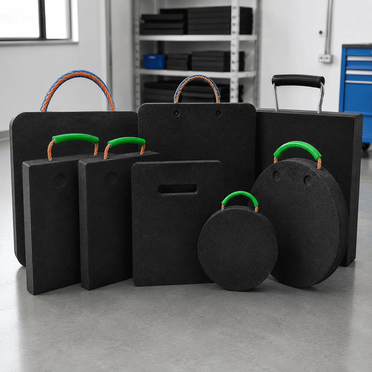
  • Black
  • Yellow
  • Blue
  • Green
  • Other project-specific colors

Different colors may help with:

  • Equipment identification
  • Organizing pad sets
  • Visual management
  • Separating different sizes
  • Matching different equipment teams

Color should not be treated as an indication of load capacity.

Different Surface Options

Different equipment applications may require different upper or lower surface structures.

Possible configurations include:

  • Circular recessed center area
  • Flat upper support surface
  • Textured working surface
  • Anti-slip surface pattern
  • Reinforced lower structure
  • Flat lower support face

The correct surface design should match the stabilizer foot, pad structure, supporting ground, and intended operating conditions.

Reusable Equipment Support Pads

A major advantage of Crane Foot Support Pads is their reusable construction.

After equipment operation is completed, the pads can be:

  • Removed from beneath the stabilizers
  • Cleaned
  • Inspected
  • Stacked
  • Transported
  • Returned to equipment storage
  • Used at another location

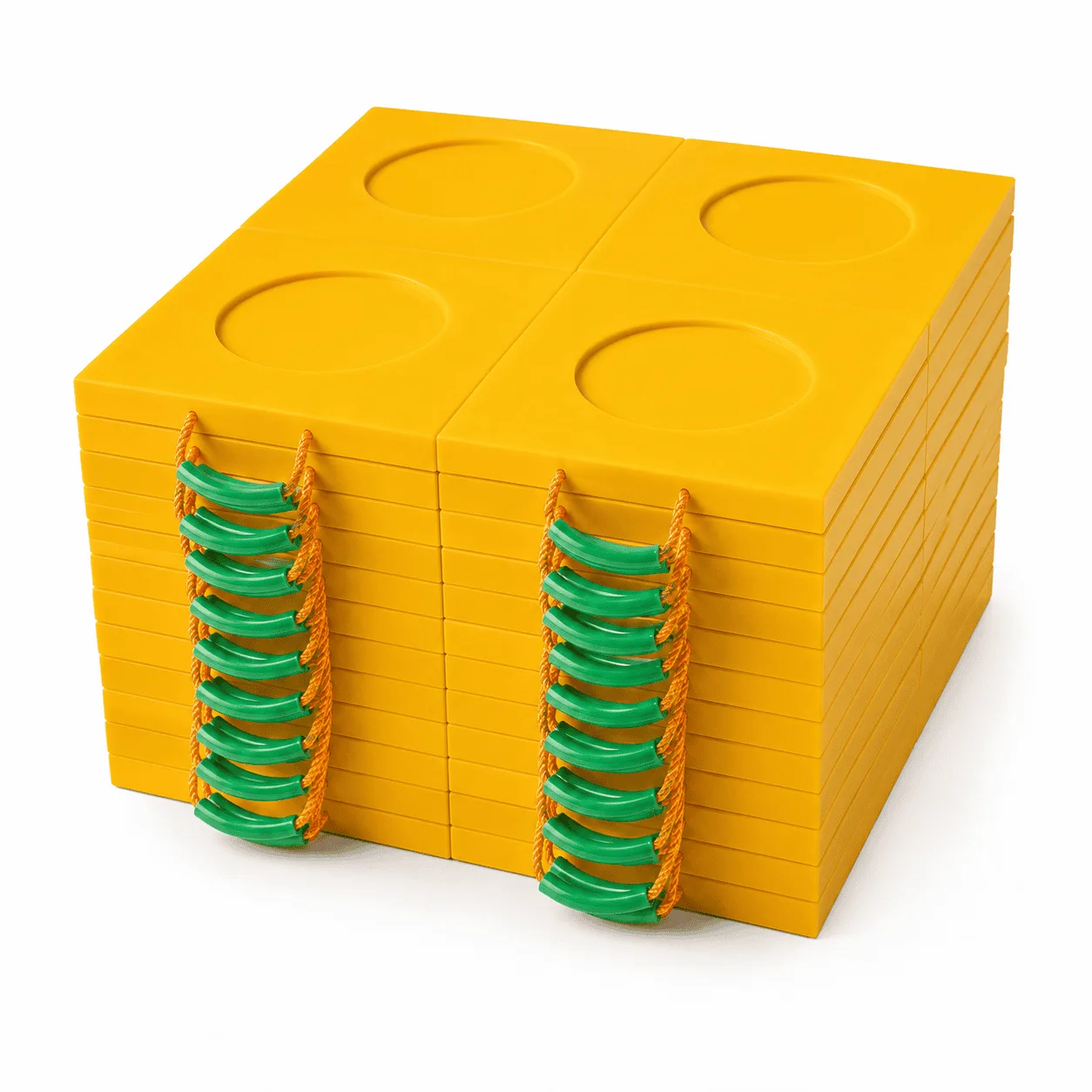
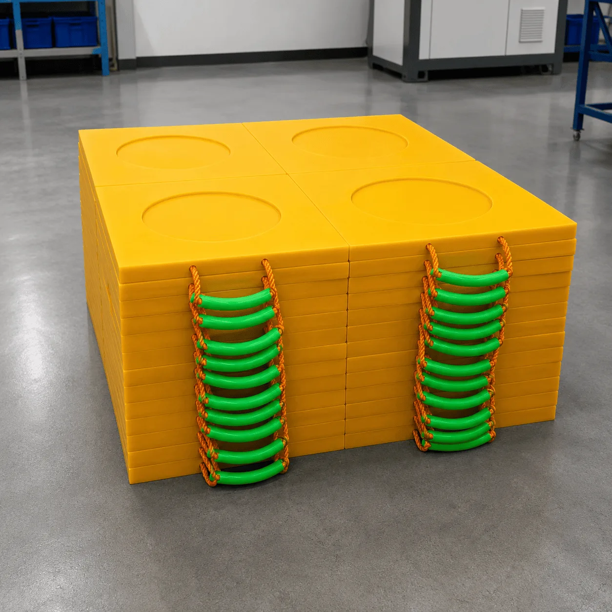
The regular square design allows multiple pads to be organized during storage and transportation.

Inspection Before Every Setup

Reusable equipment support pads should be inspected before demanding applications.

Check:

  • Upper working surface
  • Circular recessed area
  • Lower support structure
  • Pad edges and corners
  • Visible cracks
  • Severe deformation
  • Deep cuts or gouges
  • Excessive surface wear

A damaged pad should be evaluated before it returns to heavy equipment support service.

The supporting ground should also be inspected every time the equipment is repositioned.

Cleaning and Maintenance

Mud, gravel, sand, concrete residue, oil, and other debris may remain on support pads after outdoor operation.

Cleaning can help:

  • Make visual inspection easier
  • Remove debris from the recessed support area
  • Keep the lower support structure visible
  • Improve organized storage
  • Prepare the pad for the next setup

Large debris trapped beneath a support pad should be removed before equipment loading because it may create concentrated contact areas.

Storage and Transportation

Square support pads can be stacked efficiently when they are not in use.

During storage:

  • Keep complete pad sets together
  • Avoid unstable stacks
  • Separate damaged pads
  • Remove excessive mud and debris
  • Keep working surfaces available for inspection
  • Use suitable handling methods for larger pads

Handling procedures should always match the actual pad dimensions and weight.

Complete Range of Crane Outrigger Pads

You can also view our complete range of crane outrigger pads for mobile cranes, concrete pumps, boom trucks, lifting equipment, stabilizer systems, and related heavy machinery support applications.

7 Amazing Powerful Benefits of Crane Foot Support Pads

  • Large square support area for distributing concentrated stabilizer forces
  • Central circular positioning zone for more consistent equipment setup
  • Durable wear-resistant polyethylene construction for repeated outdoor use
  • Multiple sizes and thicknesses for different support requirements
  • Low water absorption and corrosion-resistant plastic structure
  • Reusable design for repeated setup, cleaning, inspection, and storage
  • Suitable for cranes, pump trucks, boom trucks, and stabilizer-equipped machinery

Why Choose Crane Foot Support Pads?

Crane Foot Support Pads provide a practical support solution for mobile cranes, truck-mounted cranes, concrete pump trucks, boom trucks, utility vehicles, and other stabilizer-equipped machinery. Their square support structure, circular recessed positioning area, wear-resistant polyethylene material, reinforced design, reusable construction, and multiple size options make them suitable for a wide range of equipment support applications.

Typical reference specifications include approximately 450 × 450 × 25 mm, 600 × 600 × 40 mm, 700 × 700 × 40–50 mm, 800 × 800 × 40–60 mm, 900 × 900 × 50–60 mm, and 1000 × 1000 × 50–80 mm. Final dimensions, thickness, material grade, effective support area, recessed structure, and lower reinforcement design should always be selected according to the maximum outrigger reaction, allowable ground pressure, stabilizer foot dimensions, supporting surface, and actual operating requirements.

Quality Control

Quality Control and Delivery Standards

Drawing & Material Check

Check drawings for full specifications and confirm materials according to service conditions to prevent product defects.

Machining Quality Control

Inspect all key processing steps and fully verify dimensions, holes, grooves and fitting surfaces.

Finishing & Batch Control

Deburr, chamfer and clean products for easy installation. Ensure uniform quality among batch products.

Packaging & Delivery

Choose appropriate packaging solutions based on product features to protect goods from collision, deformation and mixing during transit.

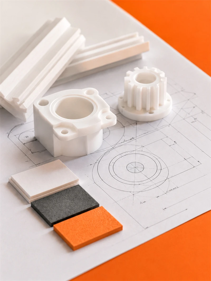
Processing Quality Control of Engineering Plastics Parts

Unlike metal parts, engineering plastic components still require strict control over dimensions, holes, edges, surface, materials and assembly performance for equipment use.

application

Applications for Engineering Plastic Parts

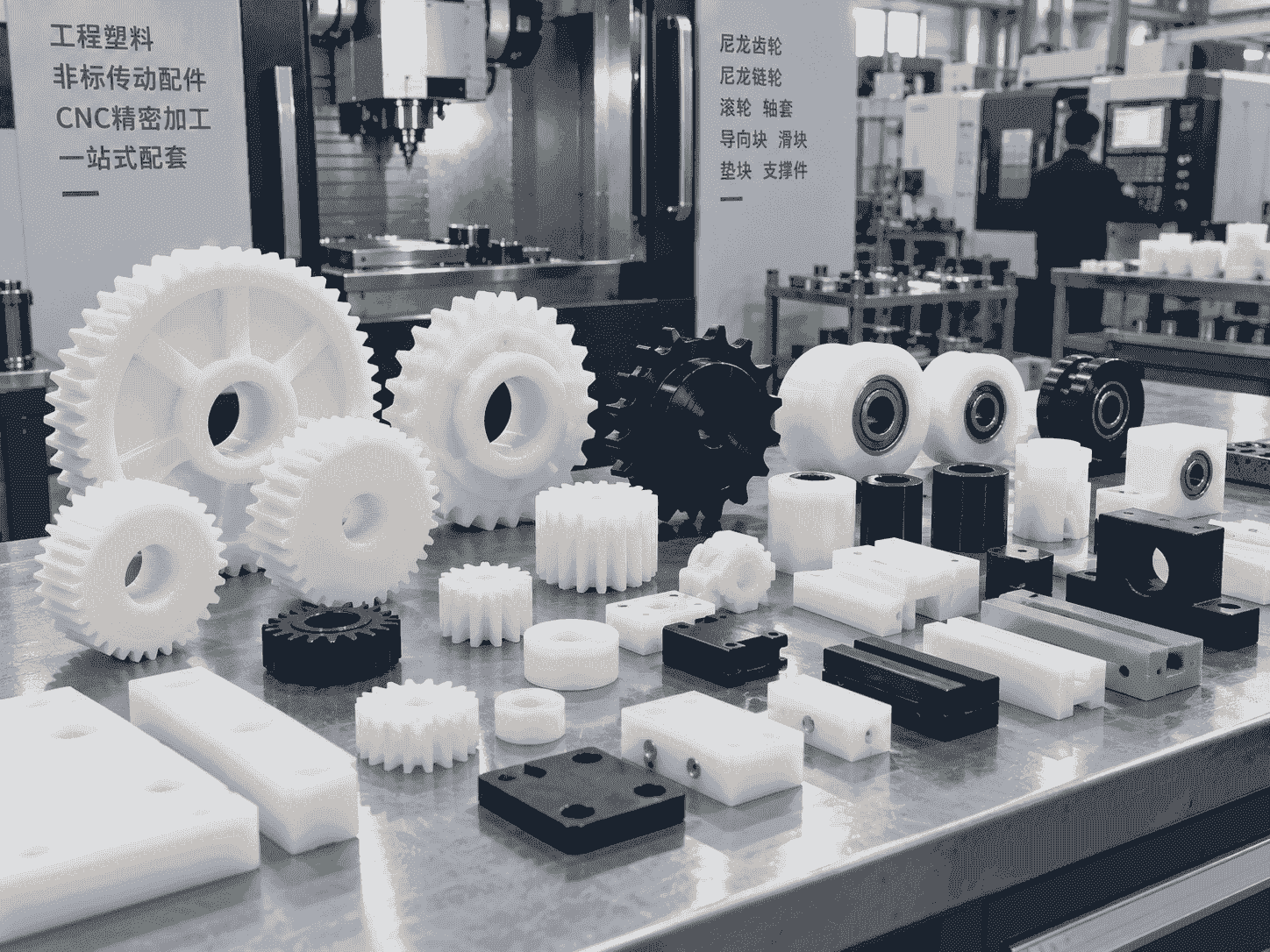
Engineering plastic parts suit friction, guide, support, buffer, anti-corrosion and insulation areas. We supply UHMWPE, POM, PA, PP/PE components for conveyor, food, mining, machinery, chemical and cable systems, with custom OEM service available.

Our Blog

Latest News & Knowledge

Stay updated with our latest industry insights, company updates and featured articles.

We Love to Hear From You

Need UHMWPE sheets & custom plastic machined/OEM parts?Send specs & material needs, free quote within 24h.