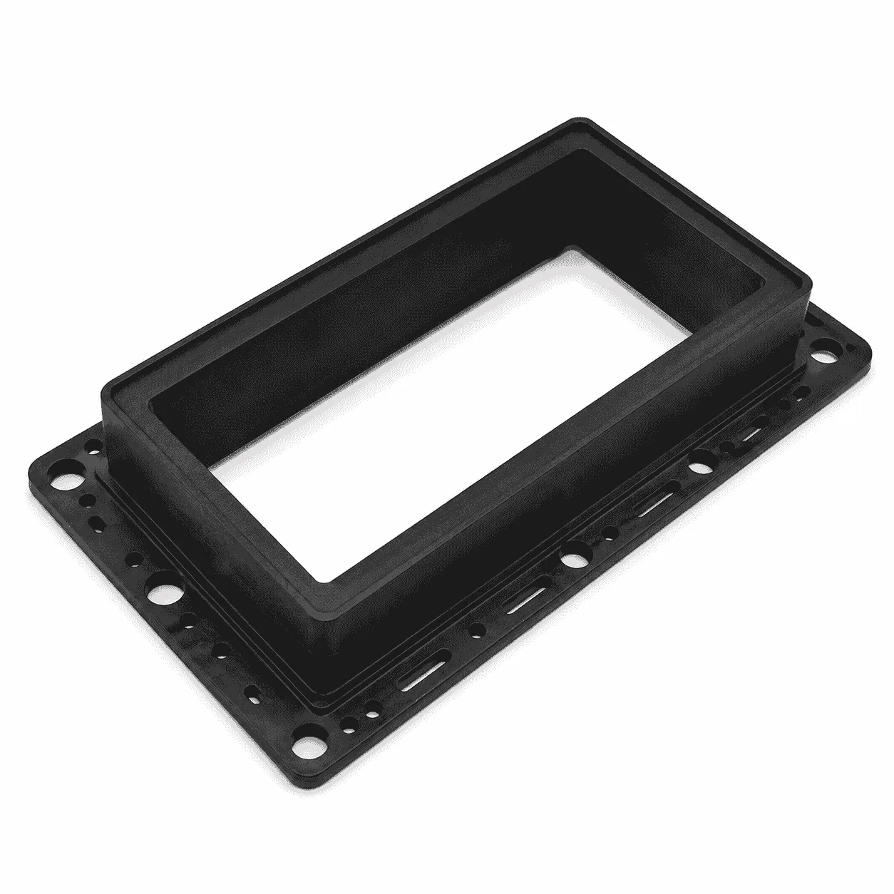
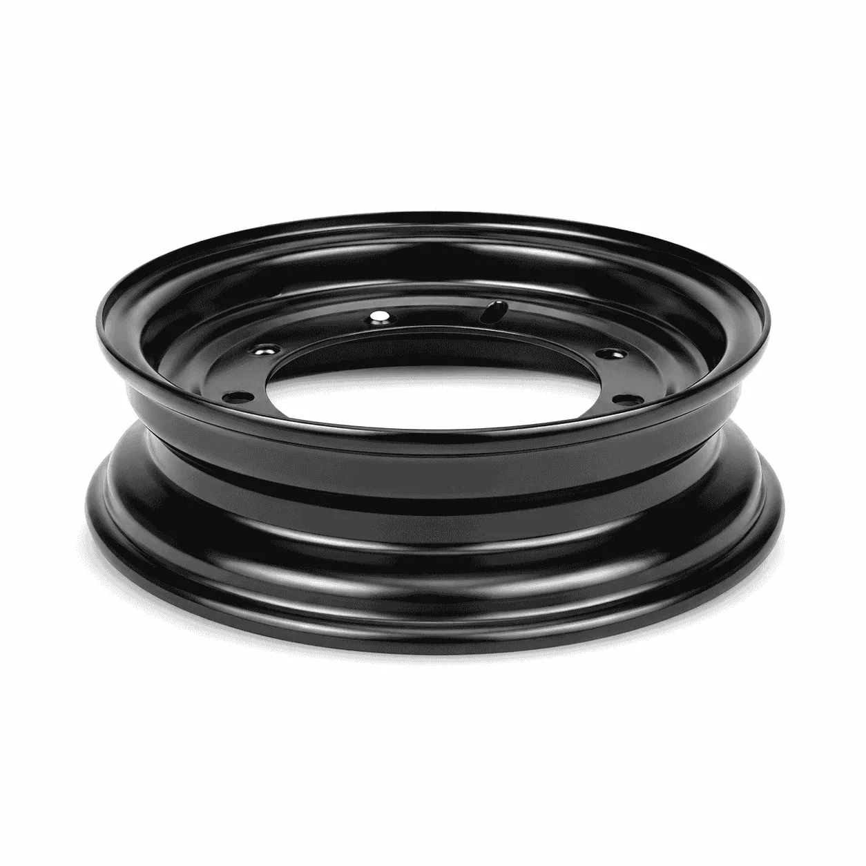
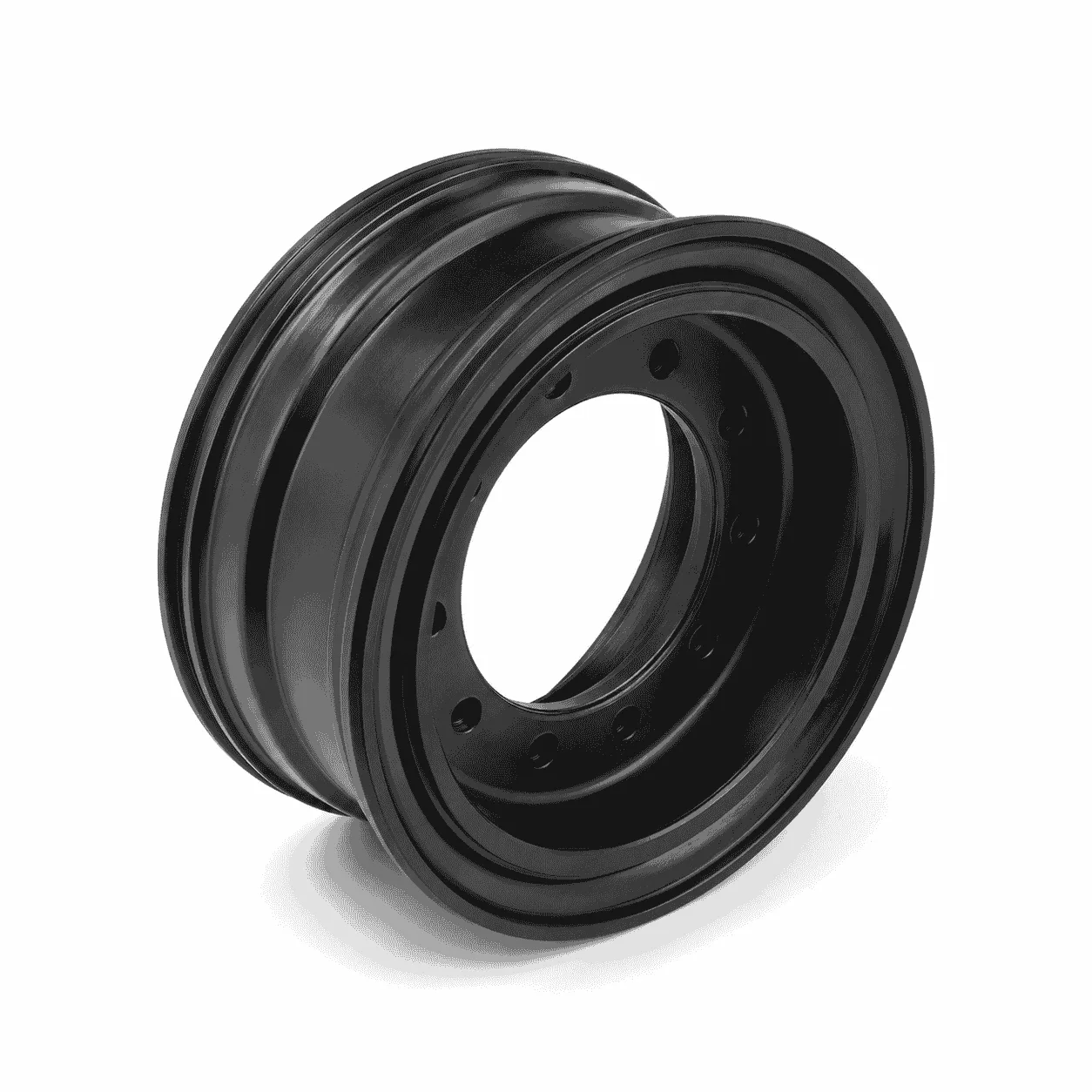
Wear-Resistant Nylon Mining Ropeway Wheel Liner for support wheels, pressure wheels and guide-wheel assemblies in mining aerial passenger ropeways. The liner provides a replaceable rope-contact surface that helps guide the steel wire rope and reduce direct contact with the metal wheel body. Groove profile, stepped structure, material grade and dimensions are produced according to drawings or physical samples.
The Nylon Mining Ropeway Wheel Liner is a wear-resistant engineering plastic component used in the wheel assemblies of mining aerial passenger ropeways, commonly known as mining chairlifts or “monkey cars.” It is installed in a corresponding support wheel, pressure wheel, guide wheel or other rope-contact wheel structure according to the equipment design.
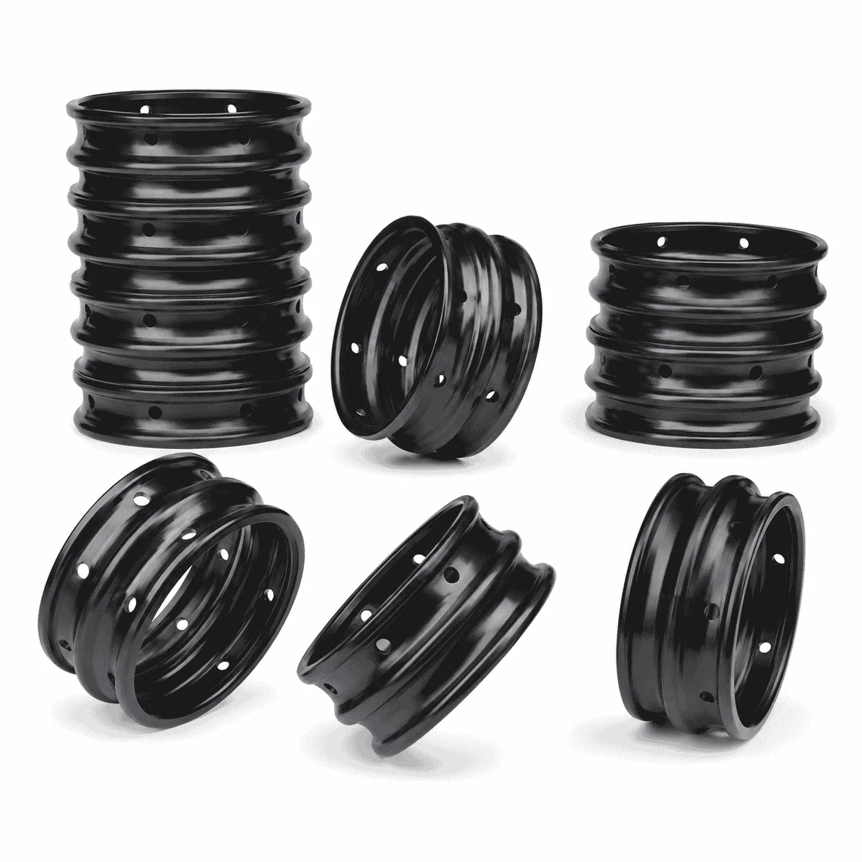
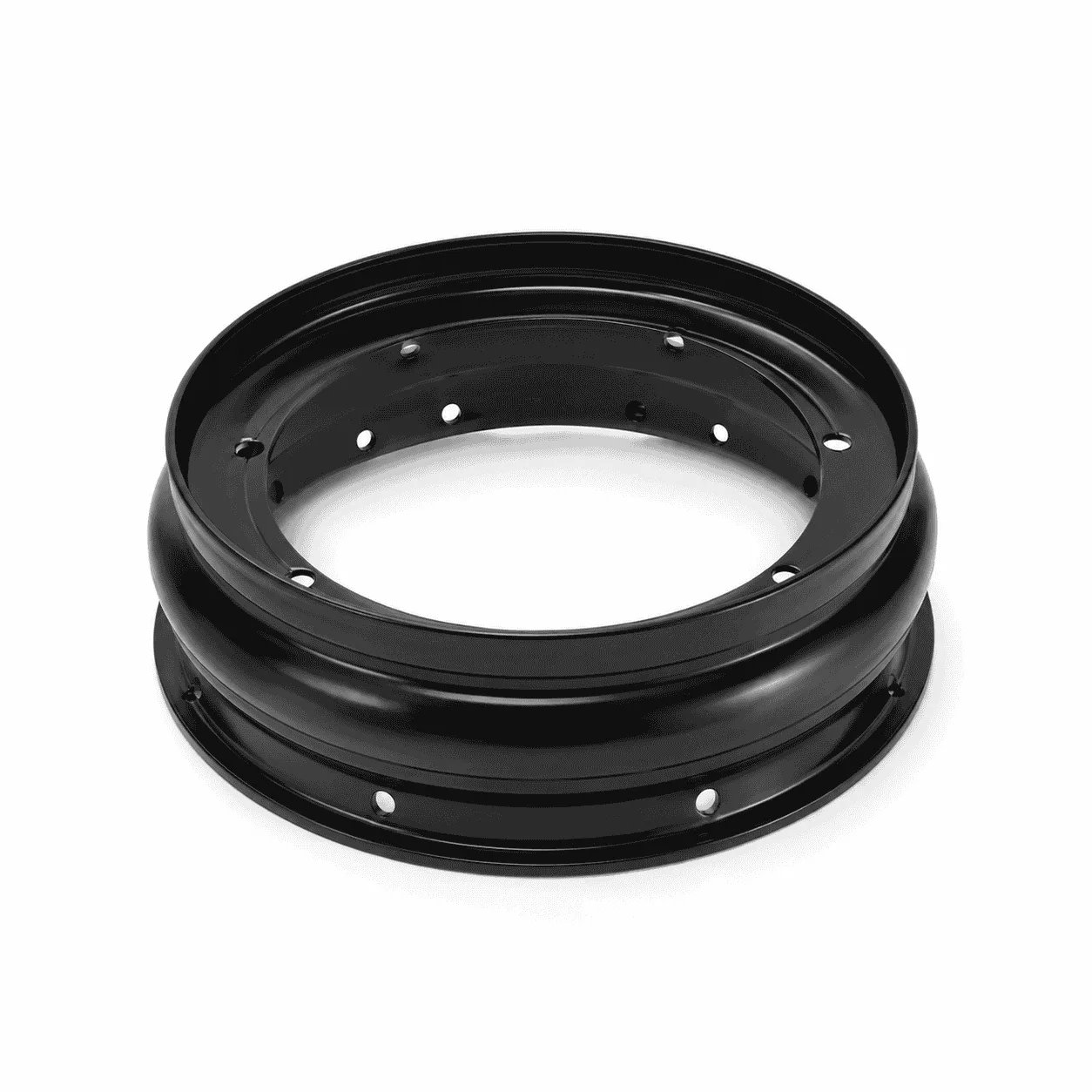
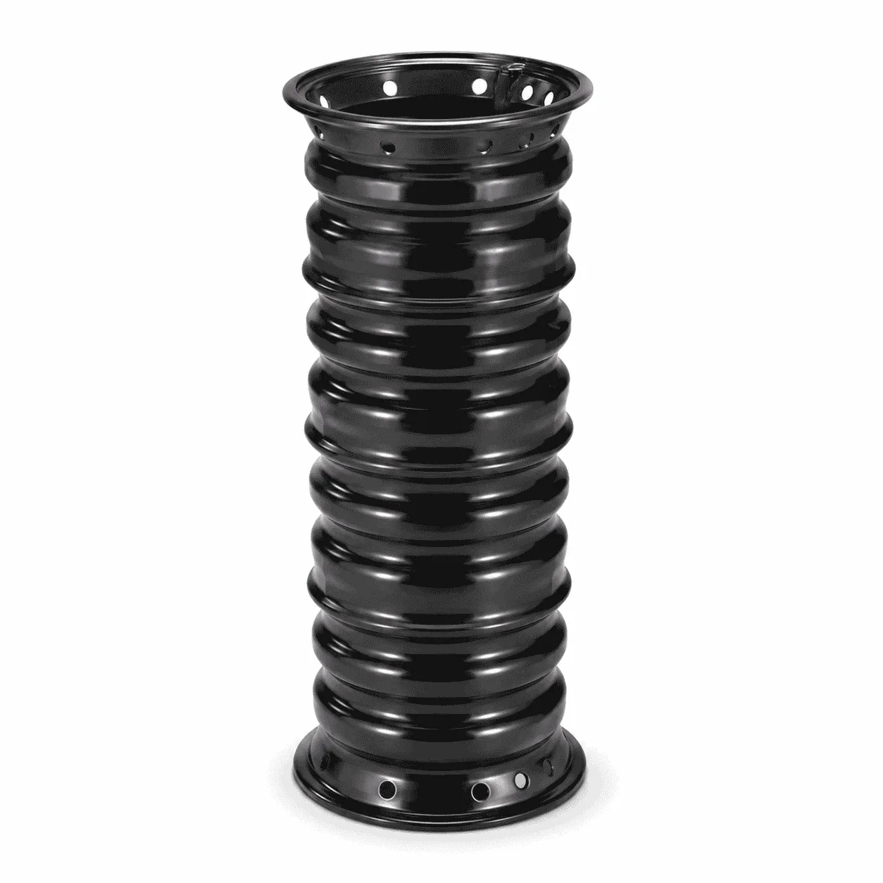
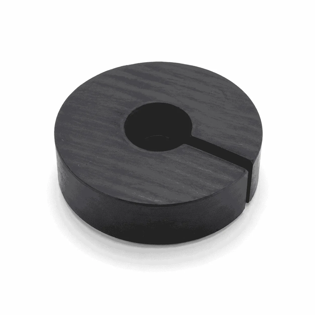
The product shown in the image has a black annular structure and is supplied in large batch quantities. Its outer and inner profiles are designed to fit the matching wheel body and provide a controlled contact surface for the steel wire rope. The exact groove, step, bore and installation structure must follow the approved equipment drawing or physical sample.
The wheel liner helps separate the steel wire rope from direct contact with the metal wheel body. Under correctly selected operating conditions, this can reduce hard impact, limit localized rope abrasion, lower running noise and provide a replaceable wear surface inside the wheel assembly.
The image does not confirm the exact nylon grade, dimensions, hardness, load rating or mining ropeway model. Final specifications must be confirmed according to the raw-material certificate, drawing, measured sample and actual operating conditions.
A mining aerial passenger ropeway normally uses a continuously moving steel wire rope to transport suspended seats or passenger carriers through an underground mine roadway. Support wheels, pressure wheels and guide wheels maintain the rope at the required height and running position.
The wheel liner is installed between the steel wire rope and the structural wheel body. Its groove or curved contact surface supports the rope while allowing it to pass through the wheel assembly. The liner may rotate together with the wheel or be installed as a replaceable contact element within the wheel structure, depending on the equipment design.
A properly matched liner should provide sufficient rope guidance without excessively squeezing the wire rope. The groove radius, groove depth, contact width and installation concentricity all influence running stability and wear distribution.
If the groove is too narrow, the steel wire rope may experience excessive side pressure and localized friction. If it is too wide, the rope may move laterally, strike the side of the wheel or operate unstably. Dimensions should therefore be matched to the specified rope diameter rather than selected only from the outside diameter of the liner.
This component can be produced from selected Polyamide PA Nylon Rod or an appropriate molded nylon blank. Possible material options include PA6, cast MC nylon, PA66, oil-filled nylon, MoS₂-filled nylon and other wear-modified polyamide formulations.
Nylon is a family of synthetic polymers characterized by repeating amide linkages. Different nylon grades can provide different combinations of mechanical strength, toughness, wear resistance, rigidity and machinability. General information about the material is available from the Wikipedia explanation of nylon.
PA6 may be considered for general-purpose wheel liners requiring balanced toughness and machining performance. Cast MC nylon may be evaluated for thicker or larger-diameter wheel liners, while PA66 may be considered where increased rigidity and mechanical strength are required.
Oil-filled nylon and MoS₂-modified nylon may be considered for selected applications involving repeated friction or reduced external lubrication. However, the final material cannot be selected only according to color. Black nylon may contain pigments, lubricating additives, wear modifiers or antistatic additives, depending on the formulation.
Commercial mining ropeway wheel liners may also be produced from polyurethane, rubber or other engineering plastics. These materials are not interchangeable in every application. Hardness, elasticity, friction, impact performance, temperature capability and compatibility with the original wheel structure must be reviewed before changing materials.
The wheel liner may be used in several wheel structures within a mining aerial passenger ropeway. The exact installation position depends on the equipment manufacturer and system configuration.
An aerial lift or ropeway uses one or more cables to carry or haul passenger carriers, cabins or open chairs. Such systems have also been used in mining applications. General system information is available from the Wikipedia explanation of aerial lifts.
The listed positions are general application references. A liner intended for a support wheel should not automatically be installed in a drive wheel, pressure wheel or safety-critical position without confirming the original design.
The Nylon Mining Ropeway Wheel Liner can be manufactured with different cross-sectional profiles to match the metal wheel body and wire-rope path.
Some industry specifications distinguish liners with and without stepped locating structures. However, terms such as H-type and G-type are not universal international size standards. The actual section profile and dimensions should be verified from the drawing or original component.
The following dimensions should be controlled according to the wheel assembly and steel wire rope specification:
The groove bottom radius should correspond to the steel wire rope diameter and equipment requirements. Incorrect groove geometry may concentrate pressure on a small part of the rope, create unstable tracking or reduce the usable liner thickness.
The fit between the liner and the metal wheel body is also important. Excessive clearance may allow relative movement, impact or rotation between the liner and wheel body. An excessively tight fit may make assembly difficult or create internal stress in the plastic component.
Through our CNC Plastic Machining service, the Nylon Mining Ropeway Wheel Liner can be produced by turning, boring, grooving, drilling, milling, chamfering and deburring according to confirmed drawings or physical samples.
Depending on the raw material and order quantity, the liner may be produced from a nylon rod, tube, molded blank or other suitable engineering plastic blank. The production method should be selected according to the finished diameter, wall thickness, material grade, batch quantity and dimensional tolerance.
Available processing details include:
Additional examples of engineering plastic components for mining equipment are available on our Mining & Bulk Material Handling application page.
For large batch orders, first-piece inspection should be completed before continuous production. The outside diameter, inside diameter, width, groove dimensions, step position and concentricity should be checked against the approved drawing.
During production, dimensional sampling should be used to monitor variation caused by tool wear, raw-material differences, temperature and internal stress. Parts from different specifications should be separated and identified to avoid mixing during wheel assembly.
The rope-contact groove should be inspected for burrs, sharp edges, cracks and excessive machining marks. Sharp groove edges may create localized contact with the steel wire rope, while burrs on the installation surface may prevent the liner from seating correctly in the metal wheel body.
Finished liners should be cleaned before packaging. Stacked products should be protected from deformation, contamination and specification mixing during storage and transportation.
Wheel liners are wear components and should be inspected regularly according to the mining ropeway maintenance procedure. Inspection should include groove wear, cracking, deformation, looseness, abnormal noise, uneven contact and movement within the metal wheel body.
A worn groove may become wider or deeper and may no longer support the wire rope at the intended position. Cracked, loose or severely deformed liners should not remain in service solely because the wheel can still rotate.
Replacement intervals vary according to wire-rope diameter, rope speed, contact pressure, wheel position, liner material, equipment alignment, environmental contamination and operating time. A universal service-life value should not be assigned without field operating data.
A mining aerial passenger ropeway is personnel-transport equipment. The wheel liner should not be selected only by appearance or approximate dimensions. Material grade, groove profile, installation fit and finished tolerances must comply with the equipment drawing and applicable maintenance requirements.
Changing from rubber or polyurethane to nylon, or changing from one nylon grade to another, may alter hardness, elasticity, friction and impact behavior. Any material substitution affecting a safety-related wheel assembly should be reviewed and approved by the equipment manufacturer or a qualified technical authority.
The product description does not establish a rated load, safety certification or compatibility with every mining ropeway model.
To manufacture the Nylon Mining Ropeway Wheel Liner accurately, please provide the outside diameter, inside diameter, overall width, groove dimensions, locating-step dimensions, nylon grade, hardness or material specification, dimensional tolerances and required quantity.
Please also provide the mining ropeway model, installation position, wheel type, metal wheel-body dimensions, steel wire-rope diameter, operating speed, environmental temperature and original component sample where available.
The image is provided as a batch-production and appearance reference only. Final material, structure, dimensions, tolerances and application suitability must follow the approved drawing, verified sample and actual mining equipment requirements.
Check drawings for full specifications and confirm materials according to service conditions to prevent product defects.
Inspect all key processing steps and fully verify dimensions, holes, grooves and fitting surfaces.
Deburr, chamfer and clean products for easy installation. Ensure uniform quality among batch products.
Choose appropriate packaging solutions based on product features to protect goods from collision, deformation and mixing during transit.
Unlike metal parts, engineering plastic components still require strict control over dimensions, holes, edges, surface, materials and assembly performance for equipment use.
Engineering plastic parts suit friction, guide, support, buffer, anti-corrosion and insulation areas. We supply UHMWPE, POM, PA, PP/PE components for conveyor, food, mining, machinery, chemical and cable systems, with custom OEM service available.
Stay updated with our latest industry insights, company updates and featured articles.

Engineering plastics are increasingly used in industrial machinery, automated production lines, conveyor systems, packaging equipment, and food-processing machines. Materials such as nylon, UHMWPE, POM, and

Both are lightweight, corrosion-resistant, wear-resistant, and suitable for CNC machining. However, they perform very differently

Wear is a common cause of failure in conveyor systems, packaging machinery, automated equipment, mining

CNC machining is widely used to produce plastic prototypes, low-volume parts, replacement components, jigs, fixtures,

Both are lightweight, corrosion-resistant, wear-resistant, and suitable for CNC machining. However, they perform very differently

Wear is a common cause of failure in conveyor systems, packaging machinery, automated equipment, mining

CNC machining is widely used to produce plastic prototypes, low-volume parts, replacement components, jigs, fixtures,
Need UHMWPE sheets & custom plastic machined/OEM parts?Send specs & material needs, free quote within 24h.