

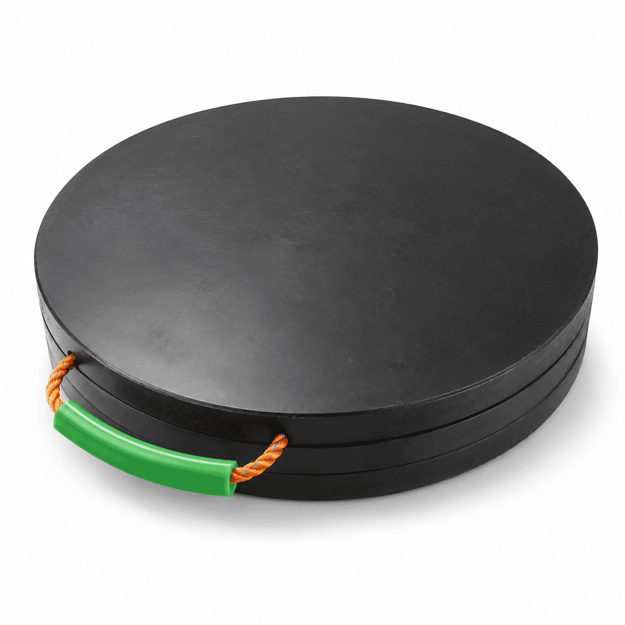
Hydraulic Outrigger Support Pads are durable UHMWPE support panels designed for mobile cranes, boom trucks, concrete pumps and other hydraulic stabilizer equipment. Round reference sizes range from approximately Ø400 × 30–40 mm to Ø1200 × 60–100 mm, with square and clipped-corner options also available. The main round design features a solid support surface and an integrated high-visibility carrying handle for repeated equipment setup.
Hydraulic Outrigger Support Pads are heavy-duty UHMWPE support panels designed for hydraulic stabilizer legs, mobile crane outriggers, boom truck support legs, concrete pump stabilizers, aerial equipment, utility vehicles, lifting machinery, and other equipment that uses hydraulic outriggers during operation.
The main product shown features a solid circular structure, a black industrial working surface, and an integrated high-visibility carrying handle. The round shape creates a symmetrical support format that is particularly suitable for circular hydraulic stabilizer feet and equipment applications where a square outside profile is not required.
The wider product family can also include square and clipped-corner support pads for different equipment configurations. This allows the pad shape, dimensions, thickness, handle structure, and working surface to be selected according to the actual hydraulic support leg and operating requirements.
Unlike temporary roadway mats, which are installed continuously to create access routes, these pads are positioned directly beneath individual hydraulic outriggers or stabilizer feet. Their primary purpose is to create a larger support interface between the original equipment foot and the underlying surface.
The exact dimensions of the circular pad shown cannot be confirmed from the image alone. The following dimensions are practical reference specifications for this type of UHMWPE hydraulic outrigger support product.
| Reference Diameter | Practical Thickness | Typical Application |
|---|---|---|
| Ø400 mm | 30–40 mm | Compact hydraulic stabilizers and smaller equipment |
| Ø500 mm | 30–50 mm | Portable service vehicles and smaller outriggers |
| Ø600 mm | 40–60 mm | General hydraulic equipment support |
| Ø750 mm | 40–60 mm | Mobile cranes and medium stabilizer systems |
| Ø800 mm | 50–80 mm | Heavy equipment hydraulic outriggers |
| Ø900 mm | 50–80 mm | Larger cranes and concrete pump stabilizers |
| Ø1000 mm | 60–80 mm | Large hydraulic support legs |
| Ø1200 mm | 60–100 mm | Large-format heavy equipment support |
The approximately Ø500 × 30–50 mm and Ø600 × 40–60 mm formats provide practical combinations of support area, portability, vehicle storage, and repeated handling.
The approximately Ø750 × 40–60 mm and Ø800 × 50–80 mm formats provide a broader geometric support area for medium and larger hydraulic stabilizer systems.
Large formats such as approximately Ø900 × 50–80 mm, Ø1000 × 60–80 mm, and Ø1200 × 60–100 mm require additional consideration for finished weight, handling, transportation, storage, material stiffness, and the complete equipment support condition.
The wider Hydraulic Outrigger Support Pads range can also include square and clipped-corner formats.
| Reference Size | Practical Thickness | Typical Shape |
|---|---|---|
| 400 × 400 mm | 30–50 mm | Square or clipped-corner |
| 500 × 500 mm | 40–60 mm | Square or clipped-corner |
| 600 × 600 mm | 40–60 mm | Square or clipped-corner |
| 760 × 760 mm | 50–80 mm | Square or clipped-corner |
| 800 × 800 mm | 50–80 mm | Square or clipped-corner |
| 1000 × 1000 mm | 60–100 mm | Square or clipped-corner |
The dimensions above are practical reference options rather than universal safe-working-load ratings.
Final dimensions should always be selected according to the maximum individual hydraulic outrigger reaction, original stabilizer foot dimensions, required support area, supporting surface, UHMWPE material structure, pad thickness, and actual operating configuration.
| Specification | Typical Reference |
|---|---|
| Product type | Hydraulic outrigger and stabilizer support pad |
| Primary material | UHMWPE |
| Main reference shape | Round |
| Other shape options | Square and clipped-corner square |
| Reference color | Black |
| Other practical colors | Yellow, red, blue and application-specific colors |
| Round diameter range | Approximately Ø400–Ø1200 mm |
| Typical thickness range | Approximately 30–100 mm |
| Handling feature | Integrated flexible carrying handle |
| Main applications | Hydraulic outriggers, mobile cranes and heavy equipment |
Final dimensions, material grade, thickness, surface structure, handle configuration, edge design, and equipment application should always be selected according to the actual operating requirements.
The main structural feature of the product shown is its solid circular shape.
A round pad can be practical where:
The circular shape creates the same outside radius around the center of the pad.
This can make visual positioning relatively straightforward when the original hydraulic support foot is also round.
Correct positioning is still important. An equipment foot positioned close to the outer edge creates a different loading condition from one positioned within the intended central working area.
Hydraulic Outrigger Support Pads are primarily intended for equipment that deploys hydraulic legs or stabilizers before operation.
Typical hydraulic support systems can be found on:
The hydraulic cylinder extends the stabilizer leg until the equipment foot transfers reaction into the supporting surface.
The support pad is positioned beneath the foot to create a larger geometric contact interface.
The correct support arrangement depends on the actual equipment reaction, pad size, pad thickness, original foot dimensions, ground condition, and equipment configuration.
Mobile cranes use hydraulic outriggers to create a wider operating base during lifting operations.
The reaction acting through each support point can change according to:
For this reason, Hydraulic Outrigger Support Pads should not be selected only according to the total crane weight.
Important factors include:
Different support positions around the same crane can experience different reactions and different underlying surface conditions.
Concrete pump trucks also use hydraulic stabilizers to create a wider operating base.
Important selection factors include:
Each hydraulic stabilizer position should be evaluated according to its actual load and supporting condition.
A single universal pad specification should not automatically be assumed to suit every support point and every pump configuration.
The main round product shown includes an integrated high-visibility carrying handle.
The green handle creates a clear gripping position when the pad needs to be:
Before moving a pad, inspect:
The carrying handle is intended for pad handling and positioning. It should not be treated as a structural component carrying the hydraulic equipment load.
Handling procedures should always match the actual finished product dimensions and weight.
The product images show that the wider support pad range can include different outside shapes.
Typical options include:
Each shape provides a different combination of geometric support area, handling, storage, and equipment compatibility.
Round pads are particularly suitable where:
Square pads can provide:
A clipped-corner design provides a shape between a full square and a round panel.
This structure can provide:
The correct shape should be selected according to the actual stabilizer foot, required support area, vehicle storage system, operating environment, and handling requirements.
The primary material used for Hydraulic Outrigger Support Pads is ultra-high-molecular-weight polyethylene, commonly abbreviated as UHMWPE.
UHMWPE is a thermoplastic polyethylene material with extremely long molecular chains. The material is known for toughness, high impact strength, very low moisture absorption, low friction, and high abrasion resistance.
For a general material explanation, see the Wikipedia article about ultra-high-molecular-weight polyethylene.
Practical UHMWPE characteristics for reusable hydraulic support pads include:
Chemical resistance should not be interpreted as universal resistance to every substance.
Actual compatibility can depend on:
Special chemical environments should be evaluated according to the real operating conditions.
Hydraulic support pads are repeatedly moved, positioned, loaded, recovered, transported, and stored.
During normal use, a support pad may experience:
UHMWPE is suitable for reusable industrial components where toughness and impact resistance are important.
Regular inspection is still required before demanding applications.
The lower surface of a hydraulic support pad may contact gravel, compacted soil, asphalt, concrete, and other working surfaces.
Repeated movement can create:
The wear resistance of UHMWPE is useful for equipment support products that need to be used repeatedly.
The pad should still be removed from demanding service if inspection identifies serious structural damage, deep cuts, severe deformation, or other unacceptable changes.
Hydraulic equipment frequently operates outdoors.
Support pads may be exposed to:
The very low moisture absorption of UHMWPE is practical for reusable outdoor support products.
The pads should still be cleaned and inspected after dirty or wet operations.
A hydraulic stabilizer transfers a concentrated reaction through the original equipment foot.
Hydraulic Outrigger Support Pads create a larger geometric contact interface beneath that foot.
The performance of the complete support arrangement depends on:
A larger pad provides a larger geometric area, but the outside dimensions alone should not be treated as a universal load-capacity guarantee.
The correct pad should not be selected only according to the total machine weight.
Important factors include:
For example, two mobile cranes with similar total vehicle weight can require different support arrangements because their boom geometry, outrigger spacing, operating radius, and individual support reactions are different.
The final product should therefore be selected according to the actual support point rather than the machine category alone.
Two round support pads with the same diameter can behave differently when their thicknesses are different.
For example, an Ø800 mm product can be considered in several reference thicknesses:
A Ø1000 mm product can use:
Thickness selection should consider:
A thinner product may be easier to move, while a thicker pad provides a different structural response.
Hydraulic Outrigger Support Pads can be used with many types of stabilizer-equipped machinery.
Typical applications include:
The correct dimensions, thickness, material grade, and shape should always be matched to the actual equipment.
Mobile cranes are one of the primary applications for hydraulic support pads.
Before setup, consider:
Each support location should be checked separately because the ground and equipment reaction may differ around the same crane.
Boom trucks frequently move between multiple operating locations.
Practical support-pad features for this equipment include:
The required pad should be selected according to the actual hydraulic support reaction and supporting surface.
Hydraulic stabilizer pads can also be used with selected aerial and utility equipment.
Typical machinery includes:
Portable round pads can be particularly practical for equipment that is repositioned frequently.
Compacted soil can vary according to moisture, previous excavation, fill material, and compaction quality.
Before positioning a support pad, inspect for:
The effective working area of the pad should receive suitable support underneath.
A larger pad cannot automatically make unsuitable ground safe.
Prepared gravel is common around mobile and industrial equipment.
Before placing the pad, check:
Large hard objects directly beneath the pad can create concentrated contact areas and should be removed before equipment loading.
Hard surfaces should also be inspected before hydraulic stabilizers are deployed.
Possible concerns include:
The visible upper surface does not always show the complete supporting condition below the equipment.
Correct positioning is important when using Hydraulic Outrigger Support Pads.
Before applying equipment load, check that:
For round pads, the circular shape provides a clear visual reference for positioning a circular stabilizer foot near the intended working center.
A major advantage of Hydraulic Outrigger Support Pads is their reusable construction.
After equipment operation, the pads can be:
The integrated handle makes the main round product easier to organize during repeated mobile equipment operations.
Reusable equipment support products should be inspected before demanding applications.
Check:
A damaged pad should be evaluated before returning to demanding hydraulic equipment support service.
Mud, sand, gravel, oil, and other debris can remain on the support pads after equipment operation.
Cleaning can help:
Large debris should be removed from the primary support surfaces before the hydraulic load is applied.
During storage:
Handling methods should always match the actual pad diameter, thickness, and finished product weight.
Large-format products may require team handling or suitable mechanical handling methods.
You can also view our complete range of crane outrigger pads for mobile cranes, concrete pumps, boom trucks, hydraulic stabilizer systems, cribbing support, and related heavy machinery applications.
Hydraulic Outrigger Support Pads provide a practical equipment support solution for mobile cranes, truck-mounted cranes, boom trucks, concrete pumps, aerial equipment, utility vehicles, and other machinery using hydraulic stabilizer legs.
The main product combines a solid round UHMWPE structure with an integrated carrying handle, while the wider range can also include square and clipped-corner support formats.
Typical round reference specifications include approximately Ø400 × 30–40 mm, Ø500 × 30–50 mm, Ø600 × 40–60 mm, Ø750 × 40–60 mm, Ø800 × 50–80 mm, Ø900 × 50–80 mm, Ø1000 × 60–80 mm, and Ø1200 × 60–100 mm.
Final dimensions, thickness, material grade, support shape, handle configuration, effective support area, and equipment setup should always be selected according to the actual hydraulic outrigger reaction, original stabilizer foot dimensions, supporting surface condition, and operating requirements.
Check drawings for full specifications and confirm materials according to service conditions to prevent product defects.
Inspect all key processing steps and fully verify dimensions, holes, grooves and fitting surfaces.
Deburr, chamfer and clean products for easy installation. Ensure uniform quality among batch products.
Choose appropriate packaging solutions based on product features to protect goods from collision, deformation and mixing during transit.
Unlike metal parts, engineering plastic components still require strict control over dimensions, holes, edges, surface, materials and assembly performance for equipment use.
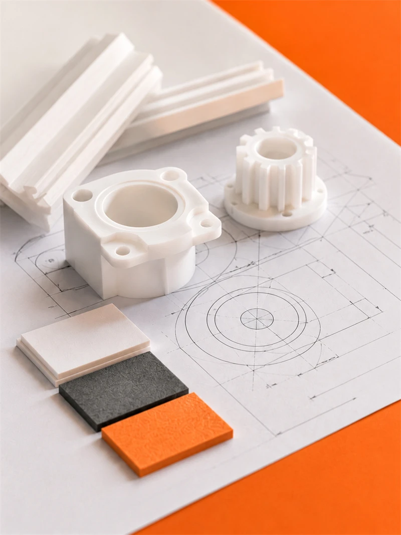
Engineering plastic parts suit friction, guide, support, buffer, anti-corrosion and insulation areas. We supply UHMWPE, POM, PA, PP/PE components for conveyor, food, mining, machinery, chemical and cable systems, with custom OEM service available.
Stay updated with our latest industry insights, company updates and featured articles.
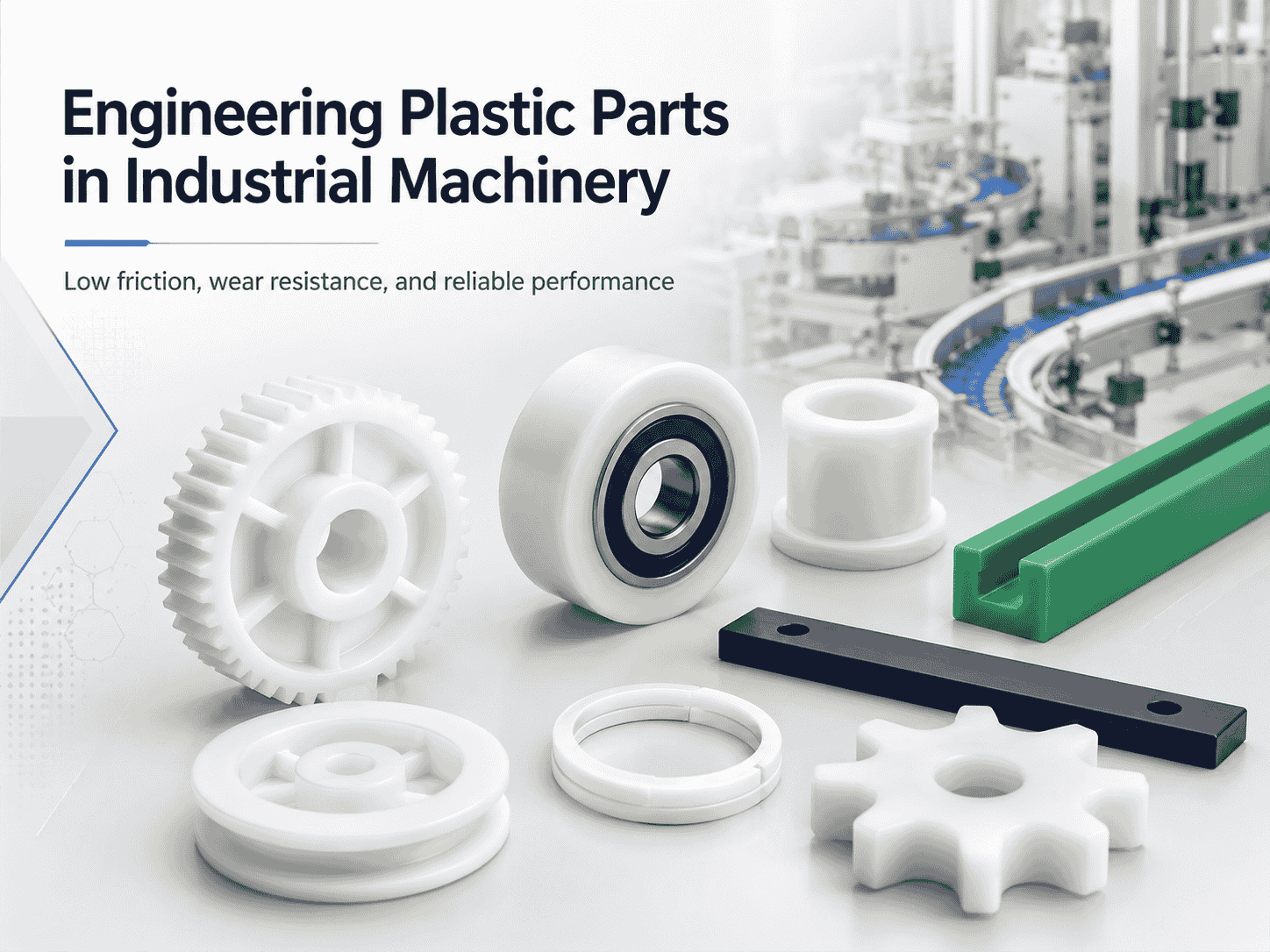
Engineering plastics are increasingly used in industrial machinery, automated production lines, conveyor systems, packaging equipment, and food-processing machines. Materials such as nylon, UHMWPE, POM, and
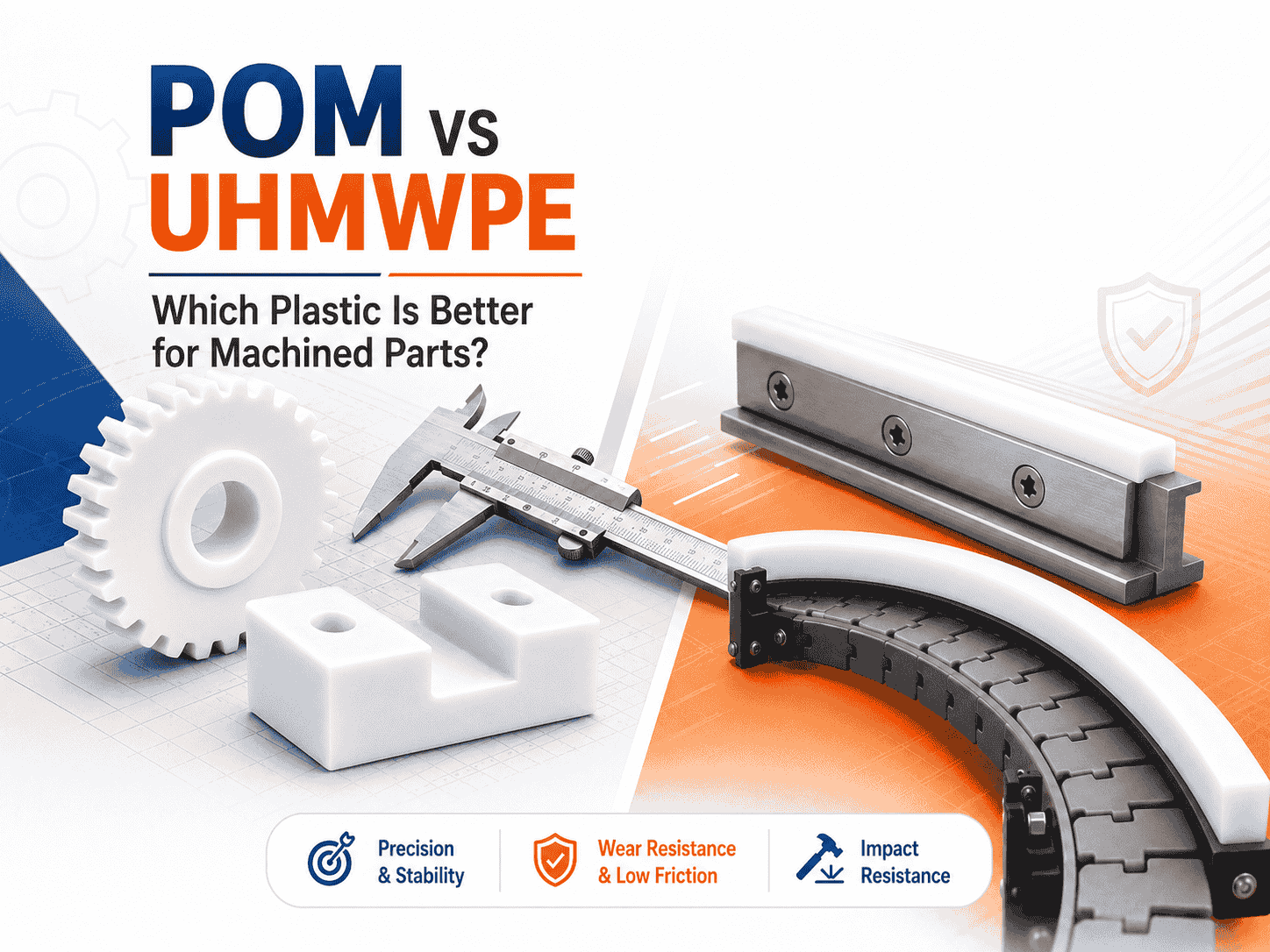
Both are lightweight, corrosion-resistant, wear-resistant, and suitable for CNC machining. However, they perform very differently
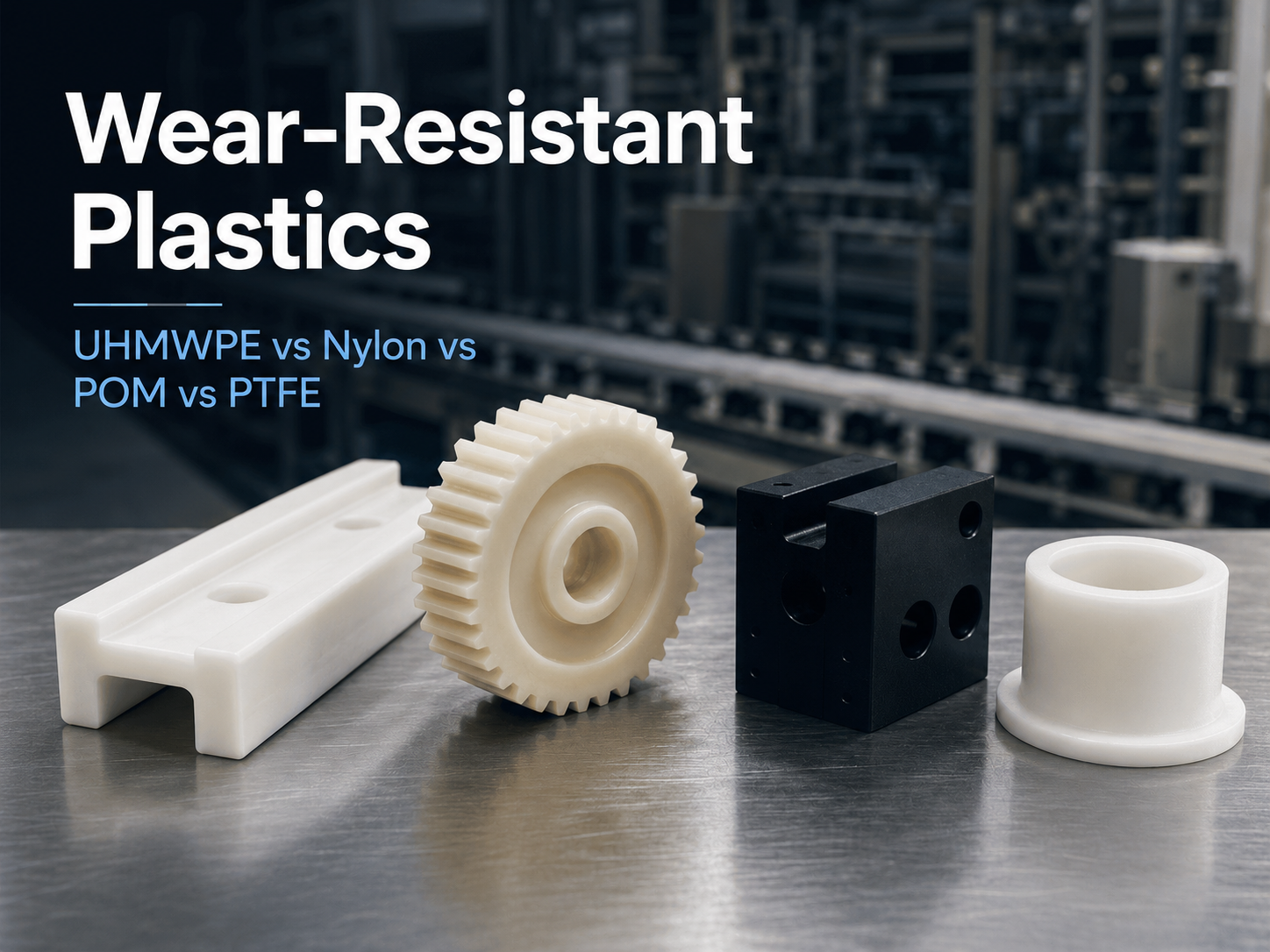
Wear is a common cause of failure in conveyor systems, packaging machinery, automated equipment, mining
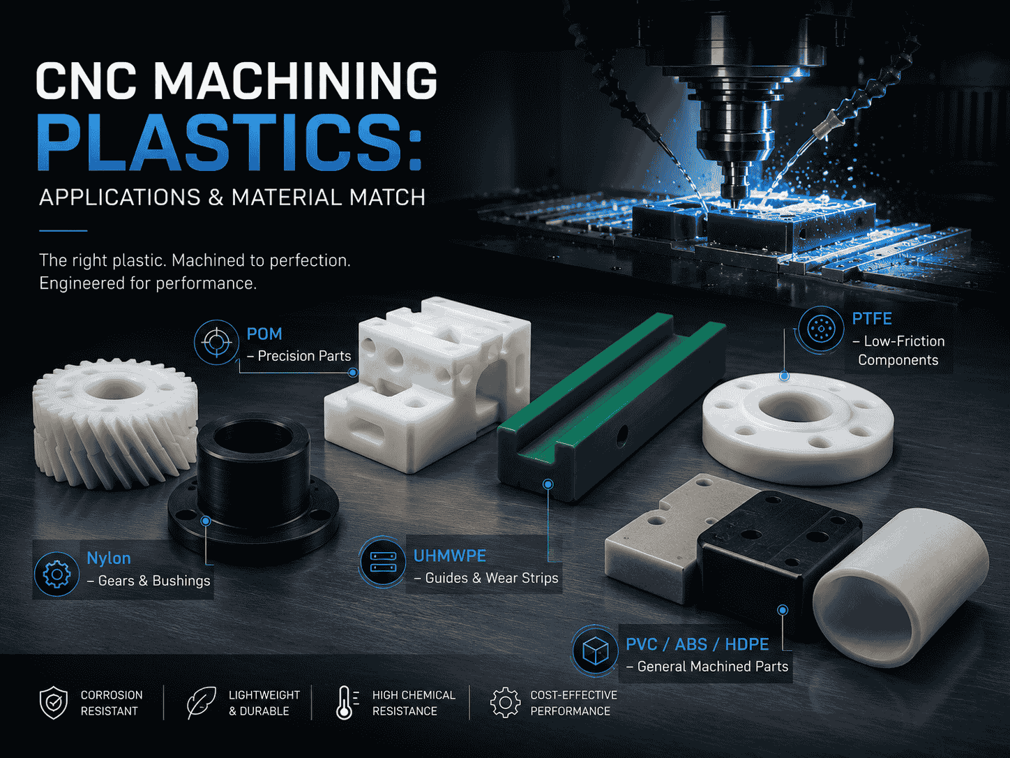
CNC machining is widely used to produce plastic prototypes, low-volume parts, replacement components, jigs, fixtures,
Both are lightweight, corrosion-resistant, wear-resistant, and suitable for CNC machining. However, they perform very differently
Wear is a common cause of failure in conveyor systems, packaging machinery, automated equipment, mining
CNC machining is widely used to produce plastic prototypes, low-volume parts, replacement components, jigs, fixtures,
Need UHMWPE sheets & custom plastic machined/OEM parts?Send specs & material needs, free quote within 24h.