

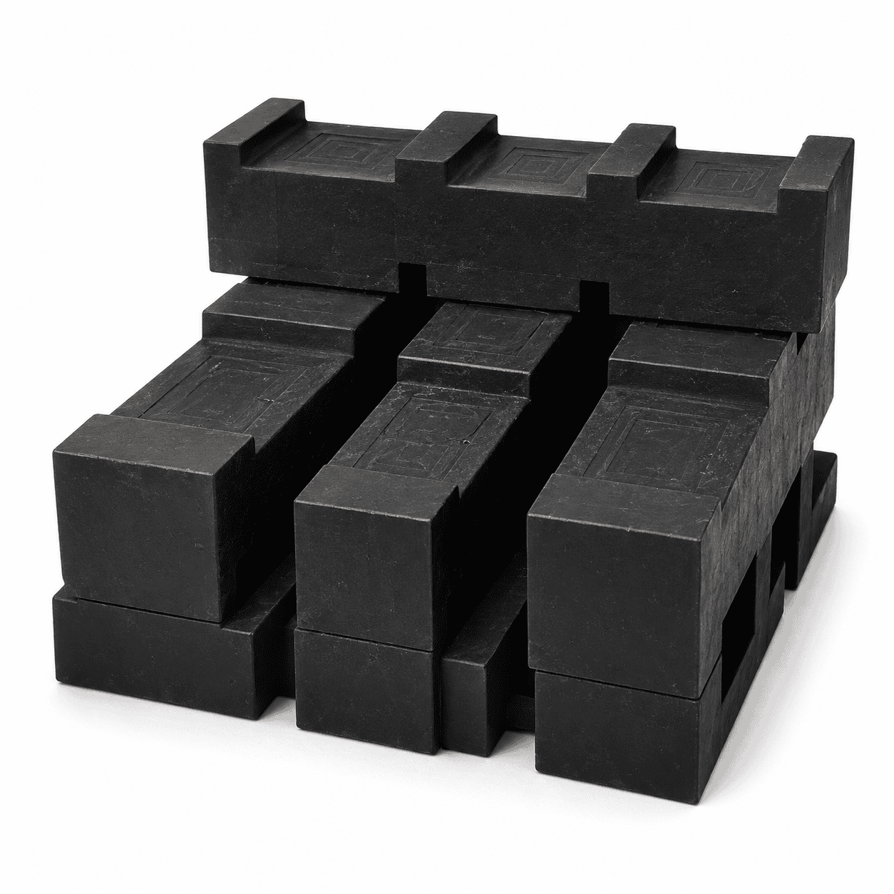
Interlocking UHMWPE Cribbing Blocks are modular heavy-equipment support components featuring raised anti-slip surfaces and mating interlocking profiles. Reference block sizes include 500 × 100 × 100 mm, 600 × 150 × 150 mm, 610 × 180 × 150 mm and 700 × 150 × 150 mm for machinery stabilization, maintenance, recovery and selected crane-support applications.
Interlocking UHMWPE Cribbing Blocks are modular engineering-plastic support components designed for temporary machinery stabilization, equipment leveling, maintenance support, recovery operations and controlled lifting or lowering applications.
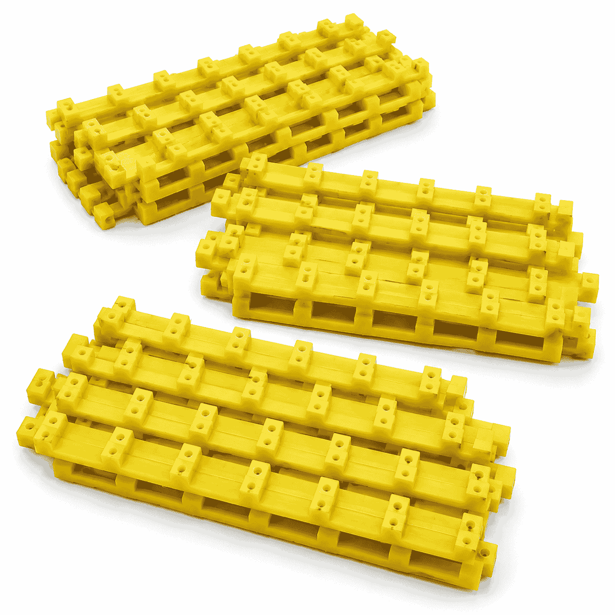
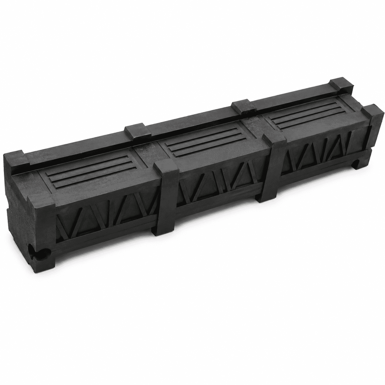
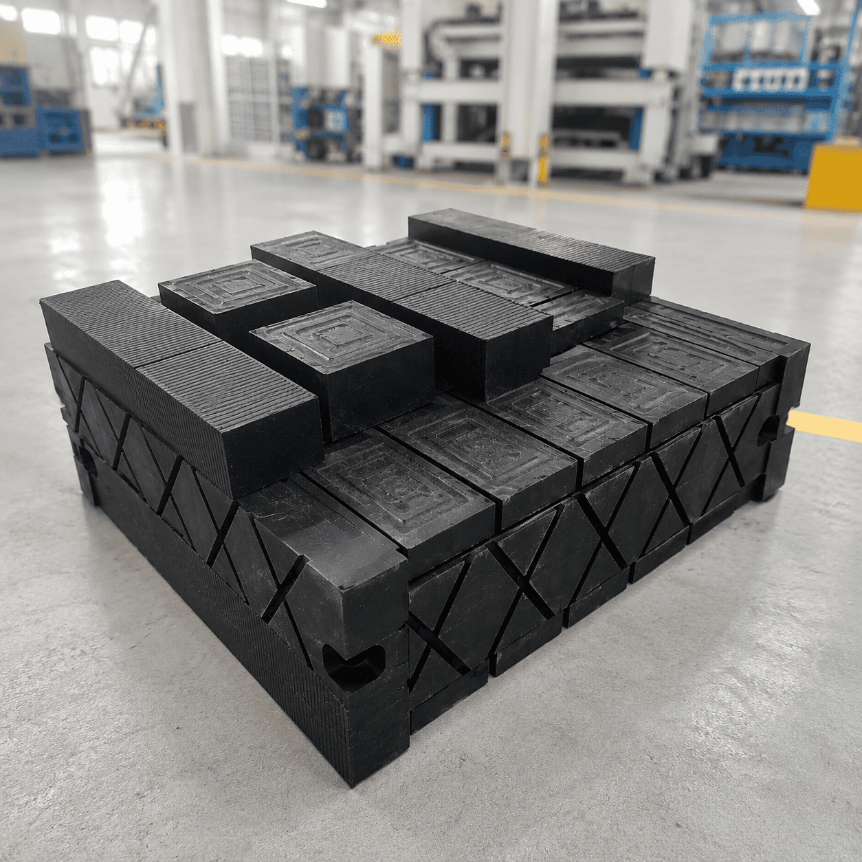
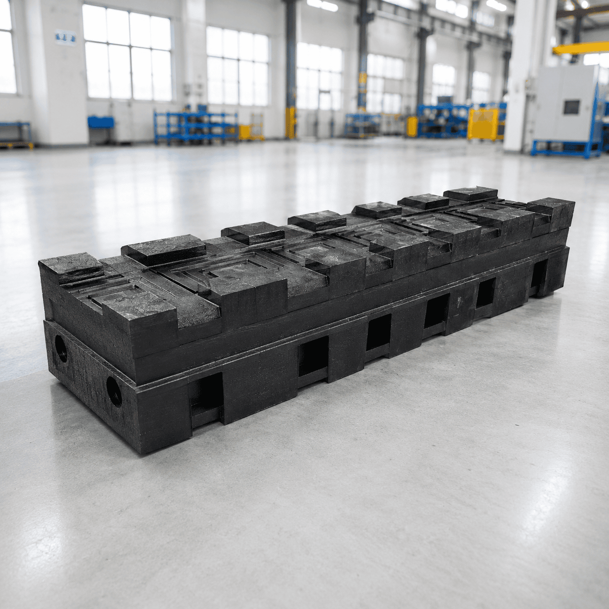
The product shown features a long rectangular structure, raised anti-slip working surfaces and interlocking profiles along the upper and lower faces. Individual blocks can be positioned parallel to each other or cross-stacked in alternating directions to create a wider and more stable cribbing structure.
Unlike a single crane outrigger pad, which is normally placed directly beneath one stabilizer foot, a cribbing-block system uses multiple modular components to build the required support height and footprint. The final arrangement should be selected according to the equipment reaction, intended stack height, block orientation, supporting surface and approved operating procedure.
The interlocking structure helps maintain alignment between adjacent layers while allowing the blocks to be dismantled, transported, inspected and reused after operation.
The precise dimensions of the blocks shown cannot be confirmed from the product photograph alone. The following dimensions are practical reference specifications for this type of modular UHMWPE cribbing system.
| Reference Block Size | Typical Positioning | Recommended Use |
|---|---|---|
| 500 × 100 × 100 mm | Compact modular block | Smaller equipment and limited storage areas |
| 600 × 150 × 150 mm | Common heavy-duty block format | General machinery and stabilizer support |
| 610 × 180 × 150 mm | Wider rectangular block | Broader cross-stacked cribbing arrangements |
| 700 × 150 × 150 mm | Extended support block | Longer equipment-support areas |
| 900 × 150 × 150 mm | Long-format support block | Selected large machinery applications |
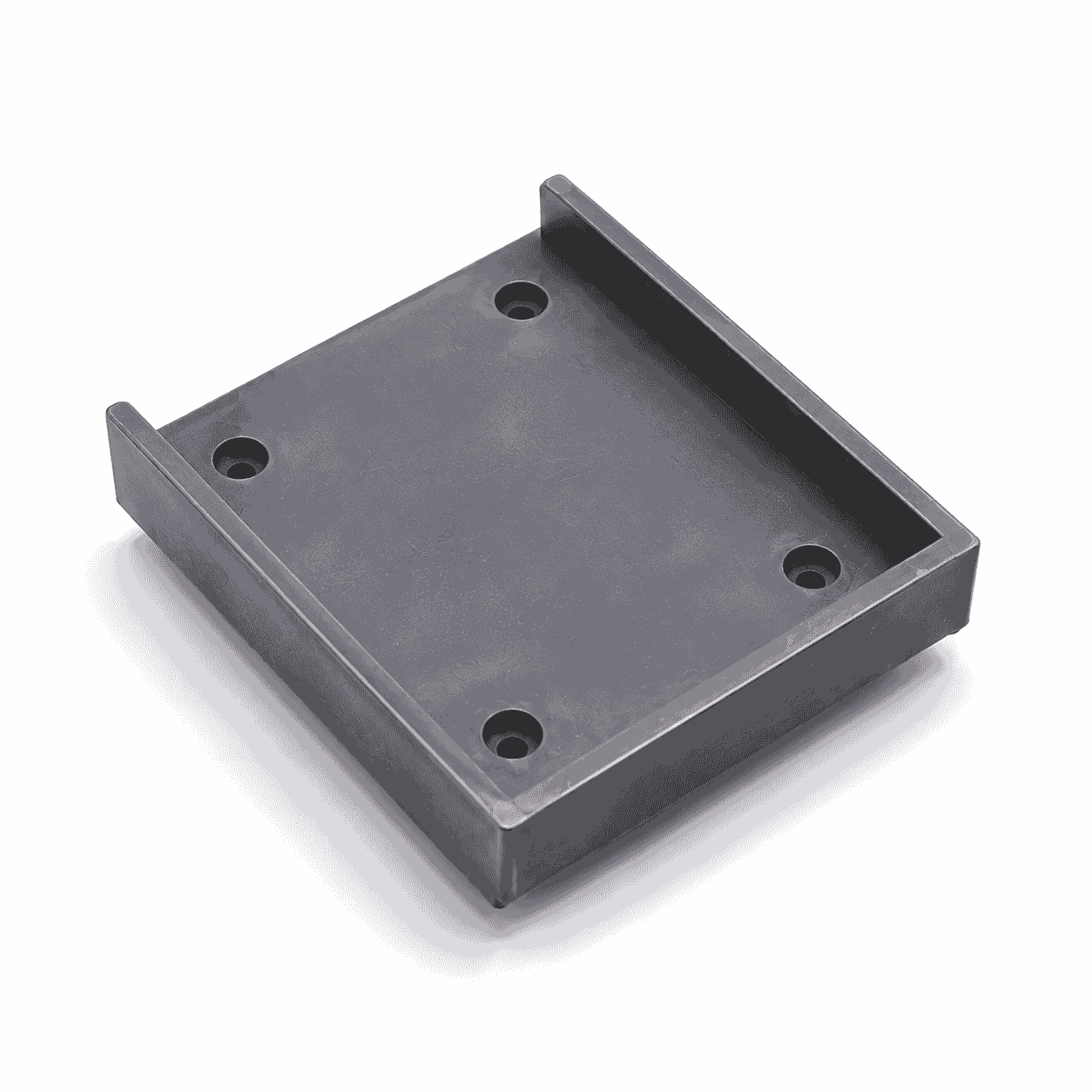
| 600 × 600 × 40–60 mm | Top or bottom support pad | Providing a broader contact surface for the crib |
| 610 × 610 × 50 mm | Top or bottom sealer pad | Matching selected 610 mm cribbing systems |
The approximately 500 × 100 × 100 mm block provides a compact option for applications where transportation space and individual handling are important.
The approximately 600 × 150 × 150 mm size is a practical reference format for modular cribbing systems. Its length allows two or more blocks to be arranged in parallel, while its height supports predictable layer construction.
The approximately 610 × 180 × 150 mm format provides a wider contact section and can be used with matching 610 × 610 mm upper or lower support pads.
Longer sizes such as approximately 700 × 150 × 150 mm and 900 × 150 × 150 mm require additional consideration for transportation, manual handling, storage and the intended cribbing footprint.
Actual finished weight depends on the selected UHMWPE grade, complete outside dimensions, internal relief features, interlocking profile, surface pattern and handle arrangement.
Final dimensions should be selected according to the equipment being supported, required footprint, intended stack height, block orientation and supporting surface condition.
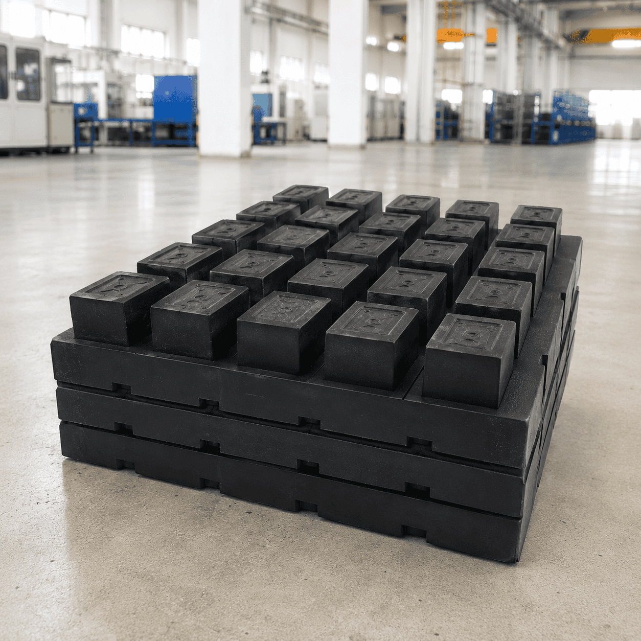
Interlocking UHMWPE Cribbing Blocks can be arranged in different modular configurations according to the required support geometry.
| Configuration | General Description |
|---|---|
| Two-block parallel layer | Two matching blocks positioned side by side in the same direction |
| Two-block cross layer | Each new layer positioned approximately 90 degrees to the layer below |
| Three-block layer | Three parallel blocks used to create a wider support footprint |
| Alternating cross stack | Parallel layers arranged in alternating directions |
| Top support pad | A larger pad positioned above the final block layer where appropriate |
| Bottom support pad | A wider pad positioned beneath the first layer where required |
The reference drawing supplied with this product family shows a modular stack with an approximately 600 mm base dimension and an approximately 912 mm overall height. This should be treated as an example configuration rather than a universal product specification.
Actual stack height depends on:
The required height should be achieved using a controlled layer arrangement rather than loosely placing unrelated blocks or filling gaps with unsuitable materials.
| Specification | Typical Reference |
|---|---|
| Product type | Modular interlocking machinery cribbing block |
| Primary material | UHMWPE |
| Main shape | Long rectangular block |
| Working surfaces | Raised anti-slip and interlocking profiles |
| Reference block length | Approximately 500–900 mm |
| Reference block width | Approximately 100–180 mm |
| Reference block height | Approximately 100–150 mm |
| Support-pad options | Approximately 600 × 600 × 40–60 mm |
| Handling options | Rope handles, flexible handles or integrated grip points |
| Stacking system | Parallel, cross-stacked or alternating modular layers |
| Main applications | Heavy machinery, recovery equipment, maintenance and equipment stabilization |
Final dimensions, material grade, surface structure, interlocking profile, handle configuration and layer arrangement should always be matched to the actual equipment and operating requirements.
The defining feature of Interlocking UHMWPE Cribbing Blocks is the modular profile formed on the upper and lower working surfaces.
Raised sections, recessed channels and mating surface features help neighboring layers remain aligned when the blocks are arranged in an approved cross-stacked structure.
The interlocking design can provide:
The interlocking profile should not be interpreted as permission to construct an unlimited stack. The permitted height, footprint and arrangement must remain suitable for the equipment load and operating procedure.
The product shown includes raised surface patterns across the primary working faces.
These textured sections provide a more pronounced industrial surface than a completely smooth block and help operators identify the intended contact areas.
The patterned surfaces can provide:
The anti-slip pattern does not replace correct block orientation, appropriate stack dimensions, a suitable supporting surface or controlled equipment loading.
Mud, oil, gravel, metal fragments and other debris should be removed before assembling the cribbing structure.
The primary material used for Interlocking UHMWPE Cribbing Blocks is ultra-high-molecular-weight polyethylene, commonly abbreviated as UHMWPE.
UHMWPE is a thermoplastic polyethylene containing extremely long molecular chains. It is associated with high toughness, impact strength, extremely low moisture absorption, low friction and strong abrasion resistance.
For a general material explanation, see the Wikipedia article about ultra-high-molecular-weight polyethylene.
Practical UHMWPE characteristics for reusable cribbing products include:
Chemical resistance should not be interpreted as universal resistance to every chemical substance. Actual compatibility depends on the chemical, concentration, exposure temperature, contact time and selected material grade.
Traditional timber cribbing can absorb moisture, splinter, crack, become contaminated and change condition during repeated outdoor use.
UHMWPE cribbing blocks provide a manufactured plastic structure with controlled dimensions and a repeatable interlocking profile.
Practical differences include:
The use of an engineering-plastic block does not eliminate the need to follow equipment-support procedures, inspect the products and confirm that the complete stack is appropriate for the intended operation.
A modular cribbing structure transfers equipment reaction through several arranged block layers toward the supporting surface.
The stability of the complete structure depends on:
A taller stack is not automatically a better support structure. Increasing height without maintaining an appropriate base footprint can reduce stability.
Each block should be fully supported by the layer beneath it, and the applied equipment reaction should remain within the intended central support area.
Selected cribbing systems can include larger top and bottom support pads.
Reference support-pad sizes include:
A bottom support pad can provide a wider initial contact area where the supporting surface and approved arrangement require it.
A top support pad can create a broader final equipment-contact surface above the last cribbing layer.
The top or bottom pad should not bridge large unsupported spaces or be used to correct an unstable stack.
Interlocking UHMWPE Cribbing Blocks can be used in controlled support and stabilization applications involving:
The correct block dimensions, layer configuration and support footprint should always be matched to the actual equipment and approved operating procedure.
Cribbing blocks can be used with selected crane and stabilizer-support arrangements where additional controlled support height is required.
Important factors include:
Cribbing blocks should not be confused with standard flat outrigger pads. A cribbing structure is a multi-component support system and requires additional attention to layer arrangement and total height.
Modular cribbing blocks can also be used for selected vehicle-recovery and maintenance support arrangements.
Possible uses include:
The correct equipment support points must be identified before the blocks are installed. Cribbing products should not be positioned beneath weak panels, unsupported covers or unapproved vehicle structures.
Before assembly, inspect the working surface and every cribbing component.
A typical modular arrangement may include the following sequence:
The stack should be assembled before the equipment reaction is fully applied. Blocks should not be forced into position beneath an unstable or moving load.
The maximum permitted stack height cannot be determined from block size alone.
Important factors include:
A narrow base combined with excessive height can create an unstable structure. The complete arrangement should maintain an appropriate relationship between its base footprint and overall height.
The applied equipment load should remain within the intended central support area of the assembled crib.
Before loading, confirm that:
An off-centre load can create a substantially different condition from a load applied near the intended centre of the cribbing structure.
Reusable cribbing blocks should be inspected before demanding equipment support operations.
Check:
Damaged components should be separated from service and evaluated before reuse.
After operation, remove mud, sand, gravel, oil and other debris from the working surfaces and interlocking profiles.
Cleaning can help:
During storage:
For flat support panels used directly beneath crane and machinery stabilizer feet, view our range of crane outrigger pads.
Interlocking UHMWPE Cribbing Blocks provide a reusable modular solution for machinery stabilization, maintenance, recovery and selected crane-support applications.
The product combines long rectangular block structures, raised anti-slip surfaces and interlocking profiles that allow matching components to be arranged in parallel or alternating cross-stacked layers.
Typical reference block sizes include approximately 500 × 100 × 100 mm, 600 × 150 × 150 mm, 610 × 180 × 150 mm, 700 × 150 × 150 mm and 900 × 150 × 150 mm. Matching top or bottom support pads can include approximately 600 × 600 × 40–60 mm and 610 × 610 × 50 mm formats.
Final block dimensions, material grade, interlocking profile, base footprint, total stack height and equipment-contact arrangement should always be selected according to the actual equipment reaction, supporting surface and approved operating requirements.
Check drawings for full specifications and confirm materials according to service conditions to prevent product defects.
Inspect all key processing steps and fully verify dimensions, holes, grooves and fitting surfaces.
Deburr, chamfer and clean products for easy installation. Ensure uniform quality among batch products.
Choose appropriate packaging solutions based on product features to protect goods from collision, deformation and mixing during transit.
Unlike metal parts, engineering plastic components still require strict control over dimensions, holes, edges, surface, materials and assembly performance for equipment use.
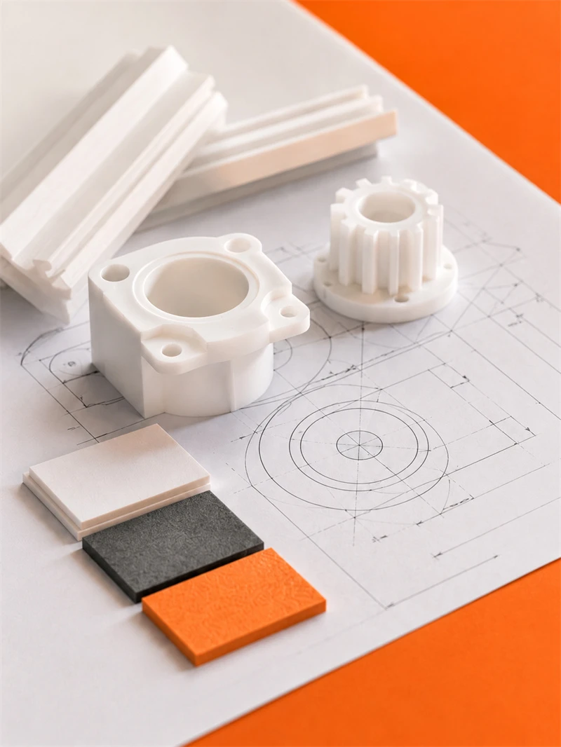
Engineering plastic parts suit friction, guide, support, buffer, anti-corrosion and insulation areas. We supply UHMWPE, POM, PA, PP/PE components for conveyor, food, mining, machinery, chemical and cable systems, with custom OEM service available.
Stay updated with our latest industry insights, company updates and featured articles.
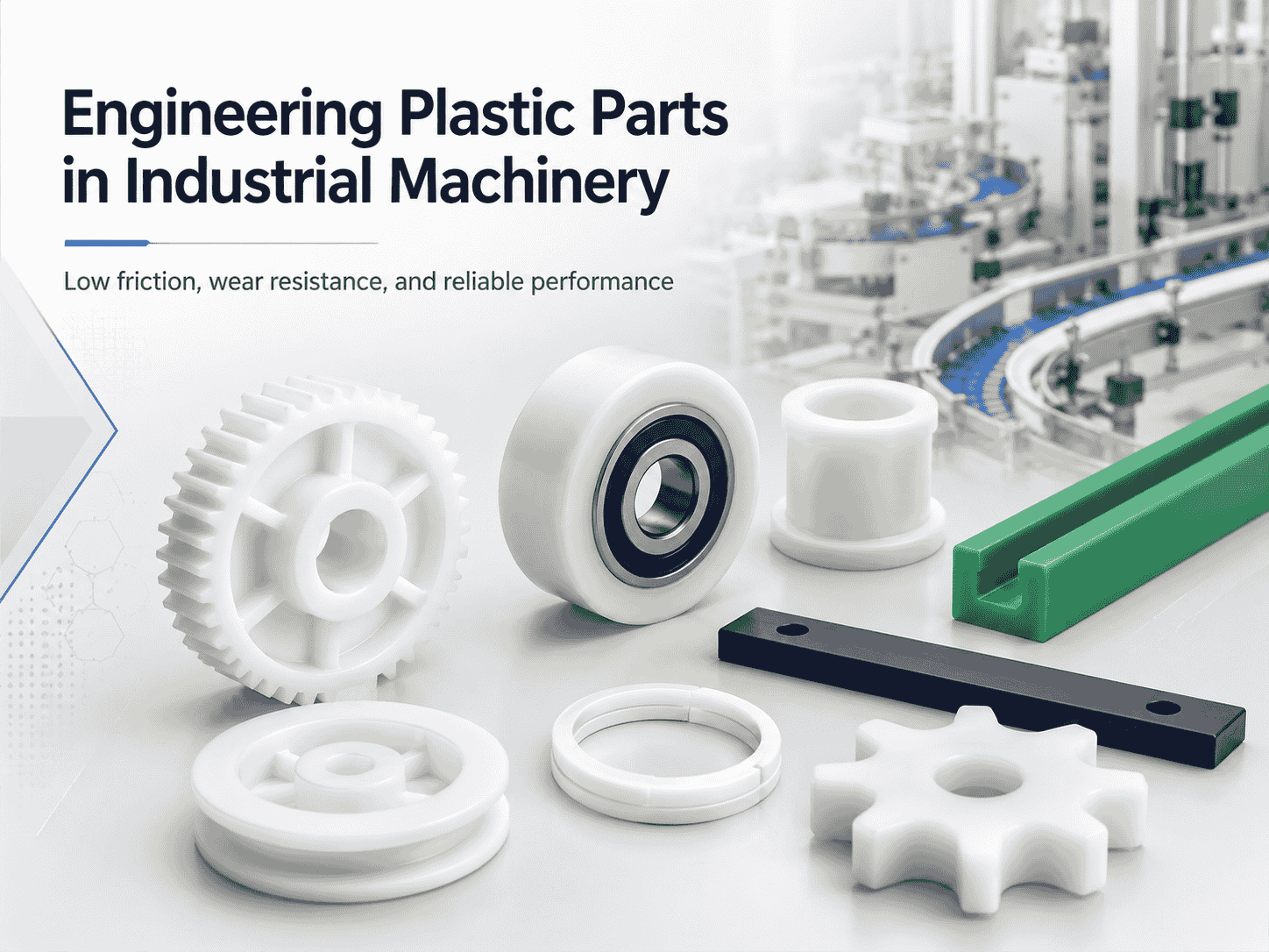
Engineering plastics are increasingly used in industrial machinery, automated production lines, conveyor systems, packaging equipment, and food-processing machines. Materials such as nylon, UHMWPE, POM, and
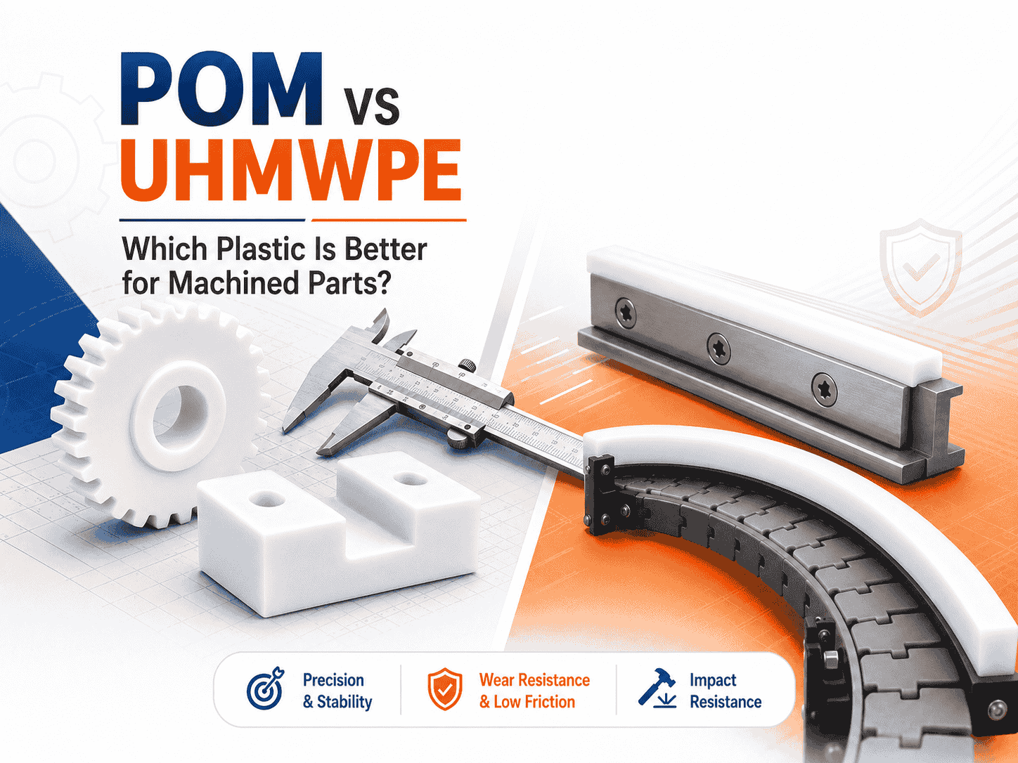
Both are lightweight, corrosion-resistant, wear-resistant, and suitable for CNC machining. However, they perform very differently
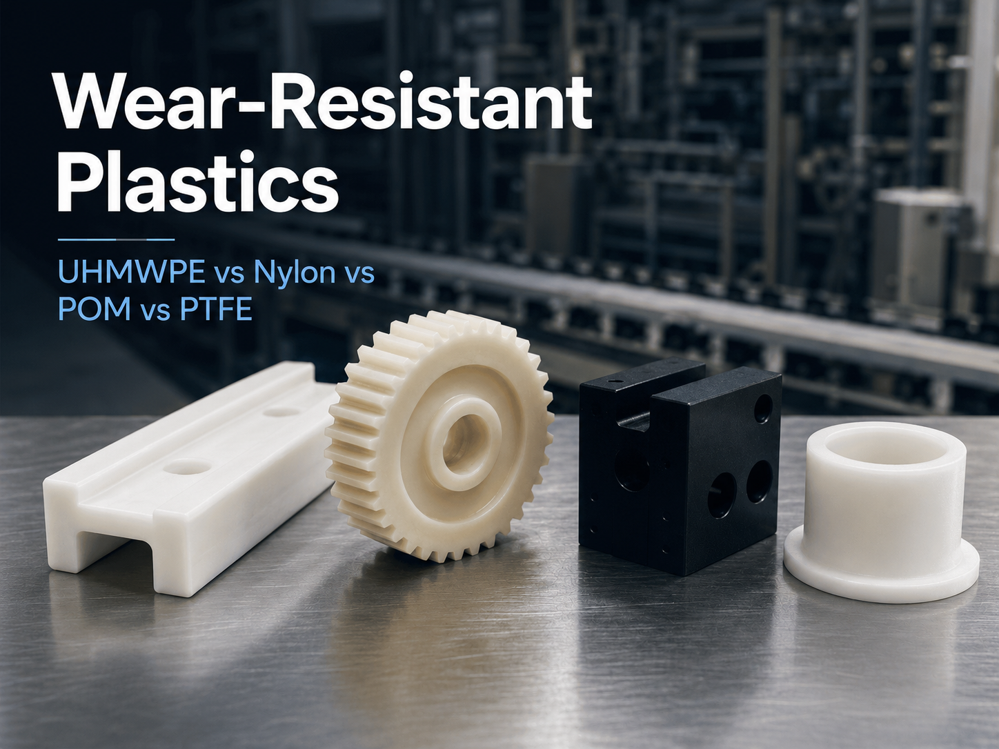
Wear is a common cause of failure in conveyor systems, packaging machinery, automated equipment, mining
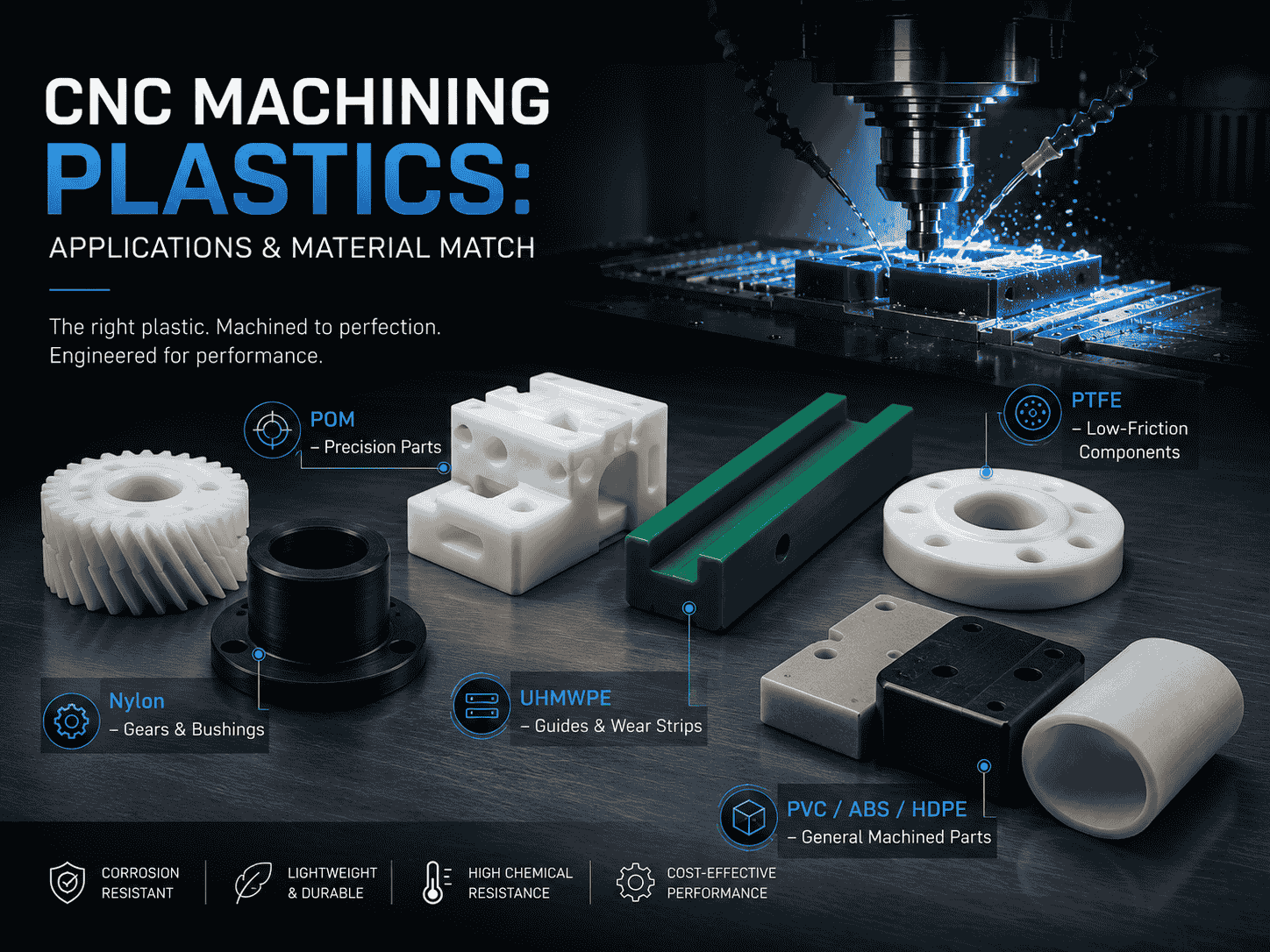
CNC machining is widely used to produce plastic prototypes, low-volume parts, replacement components, jigs, fixtures,
Both are lightweight, corrosion-resistant, wear-resistant, and suitable for CNC machining. However, they perform very differently
Wear is a common cause of failure in conveyor systems, packaging machinery, automated equipment, mining
CNC machining is widely used to produce plastic prototypes, low-volume parts, replacement components, jigs, fixtures,
Need UHMWPE sheets & custom plastic machined/OEM parts?Send specs & material needs, free quote within 24h.