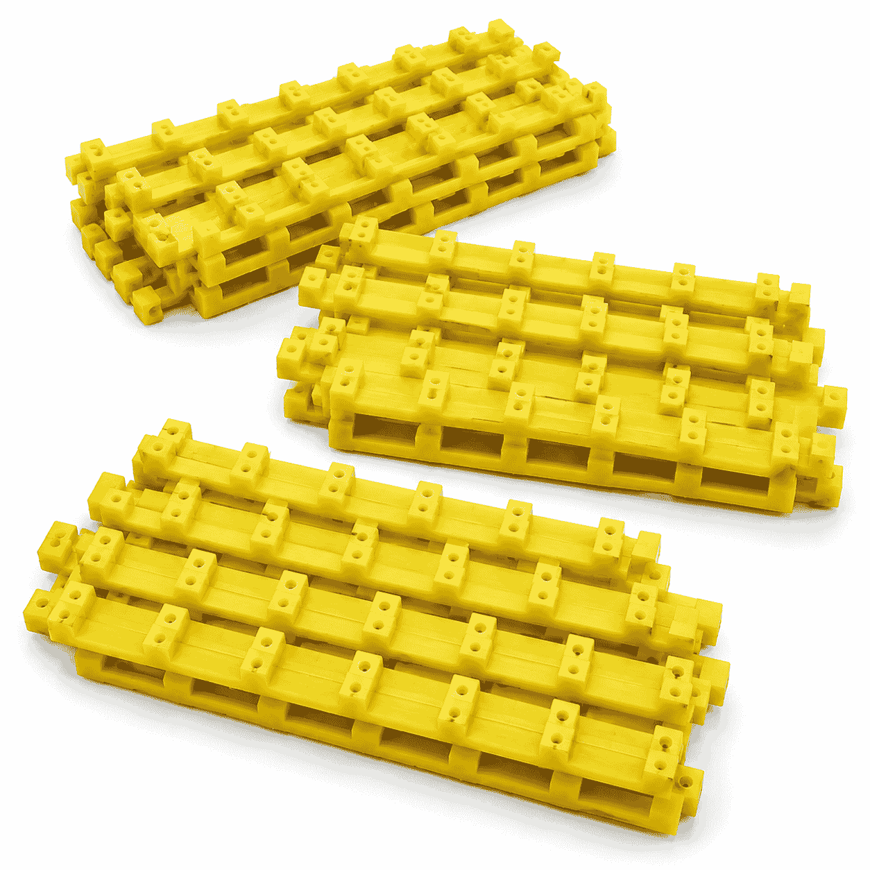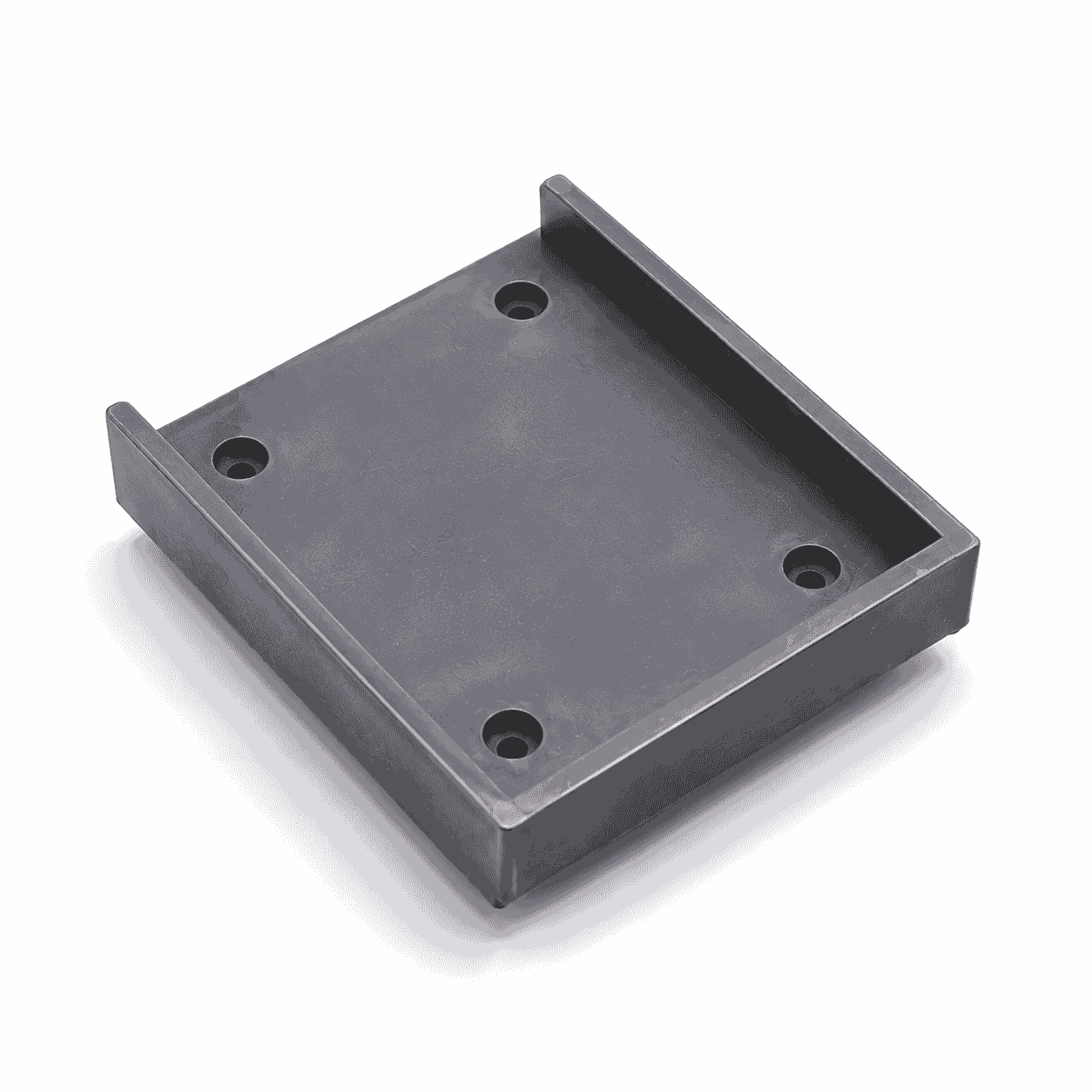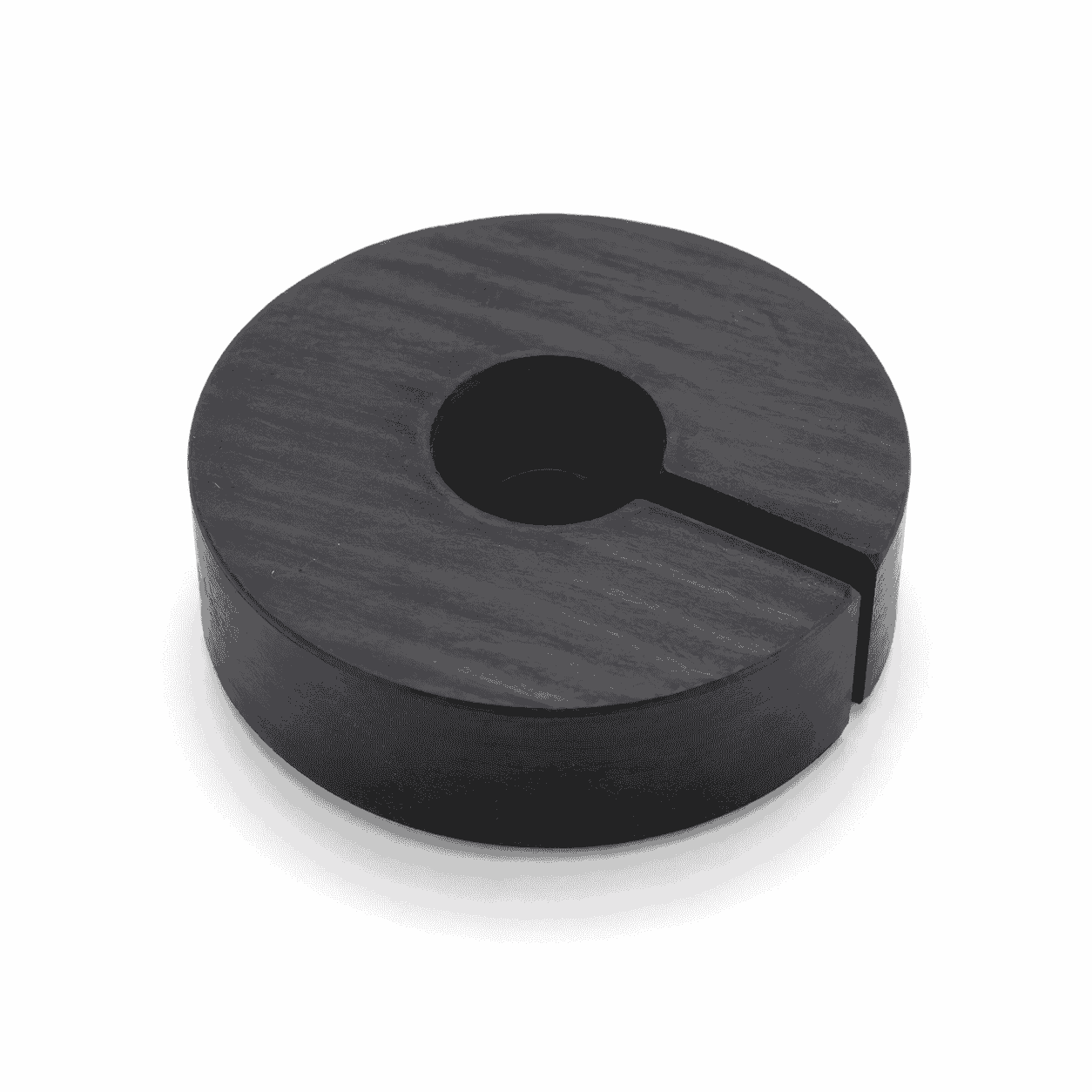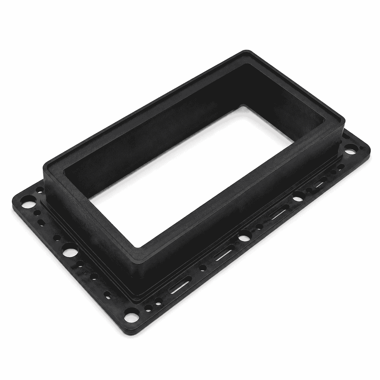


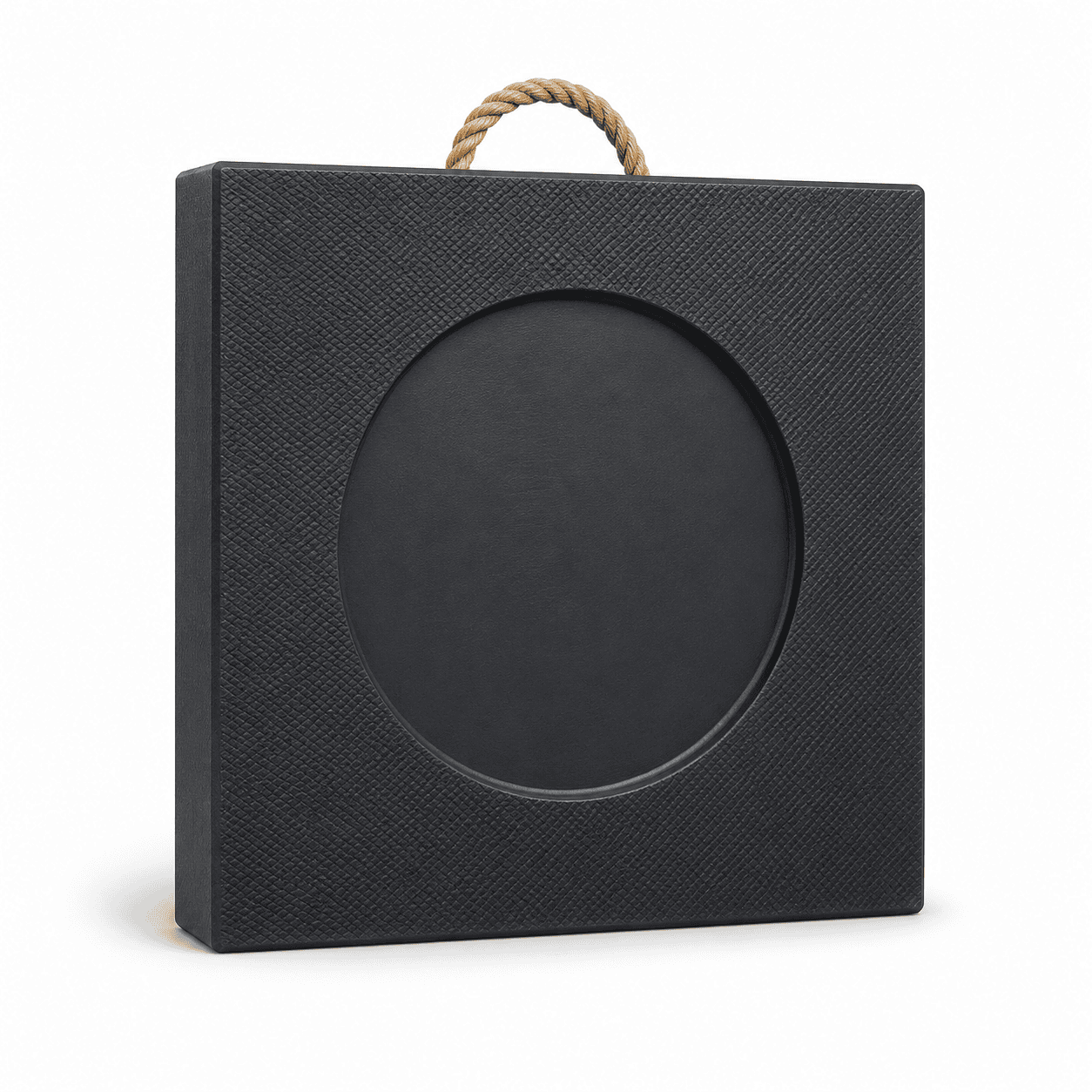
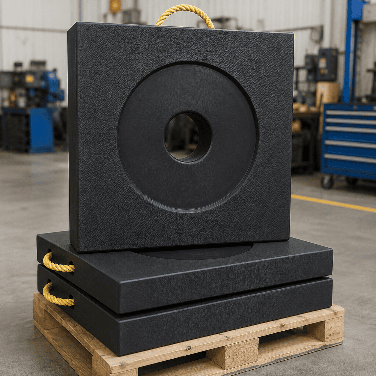
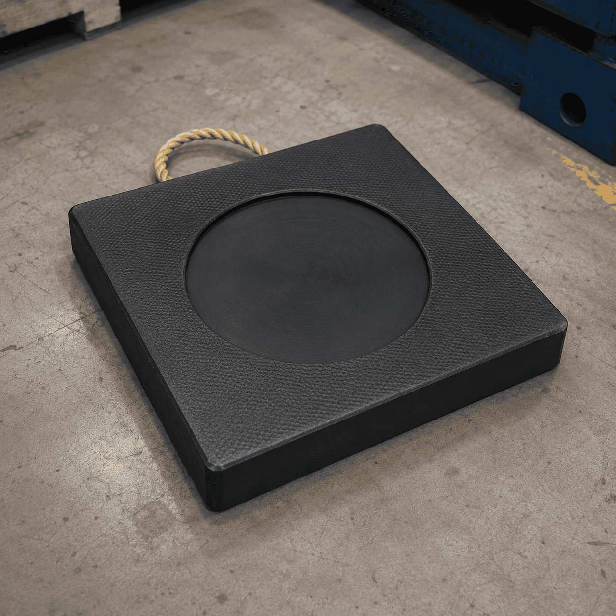
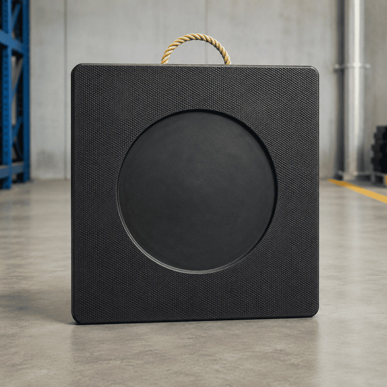
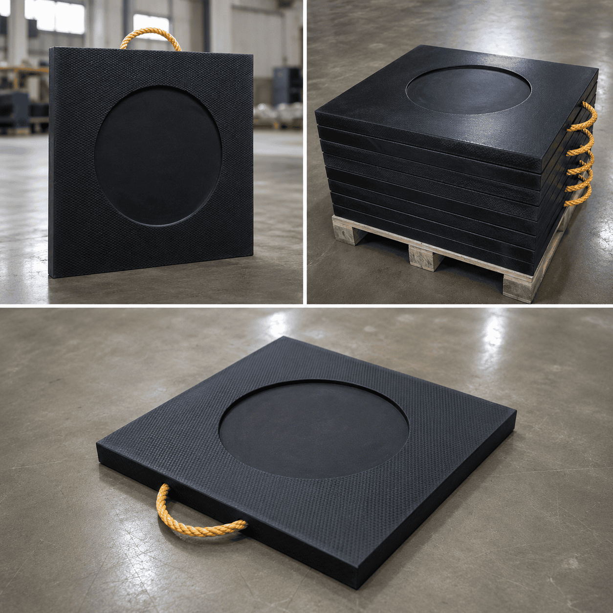
Center Hole UHMWPE Outrigger Pads are solid reusable support panels designed for cranes, concrete pumps, boom trucks and hydraulic stabilizer systems. Reference sizes range from 300 × 300 × 30 mm to 2000 × 2000 × 100 mm, while the center-hole diameter and structure are produced according to the equipment foot or approved drawing.
Center Hole UHMWPE Outrigger Pads are solid engineering-plastic support panels designed for mobile crane outriggers, hydraulic stabilizer legs, concrete pump trucks, boom trucks, aerial work platforms and other heavy machinery equipped with support feet.
The defining feature of this product is the hole positioned in the middle of the support panel. Depending on the equipment design, the center hole may be used as a positioning opening, clearance opening or installation reference for a compatible stabilizer-foot structure.
The supplied specification table provides multiple square pad dimensions, unit weights and reference load values. However, the source information does not state the diameter of the center hole or clearly identify the unit used for the load-capacity column. The final hole diameter, hole depth, panel thickness and permitted load must therefore be confirmed according to the approved drawing and actual equipment requirements.
The primary material is ultra-high-molecular-weight polyethylene, commonly abbreviated as UHMWPE. It is suitable for reusable support products that require high impact toughness, abrasion resistance, low moisture absorption and corrosion-resistant plastic construction.
The following table reproduces the main dimensional, weight and reference-capacity information shown in the supplied product data. The capacity figures are retained as source reference values because the unit is not clearly marked in the supplied image.
| No. | Dimensions | Reference Unit Weight | Source Reference Capacity |
|---|---|---|---|
| 1 | 300 × 300 × 30 mm | 2.7 kg | 5 |
| 2 | 400 × 400 × 30 mm | 4.8 kg | 10 |
| 3 | 300 × 300 × 40 mm | 3.6 kg | 8 |
| 4 | 400 × 400 × 40 mm | 6.4 kg | 15 |
| 5 | 500 × 500 × 40 mm | 10 kg | 18 |
| 6 | 600 × 600 × 40 mm | 14.4 kg | 30 |
| 7 | 1000 × 1000 × 40 mm | 40 kg | 40 |
| 8 | 400 × 400 × 50 mm | 8 kg | 18 |
| 9 | 500 × 500 × 50 mm | 12.5 kg | 20 |
| 10 | 600 × 600 × 50 mm | 18 kg | 35 |
| 11 | 800 × 800 × 50 mm | 32 kg | 40 |
| 12 | 1000 × 1000 × 50 mm | 50 kg | 55 |
| 13 | 1200 × 1200 × 50 mm | 72 kg | 60 |
| 14 | 500 × 500 × 60 mm | 15 kg | 30 |
| 15 | 600 × 600 × 60 mm | 21.6 kg | 40 |
| 16 | 800 × 800 × 60 mm | 38.4 kg | 50 |
| 17 | 1000 × 1000 × 60 mm | 60 kg | 80 |
| 18 | 1200 × 1200 × 60 mm | 86.4 kg | 100 |
| 19 | 600 × 600 × 80 mm | 28.8 kg | 65 |
| 20 | 800 × 800 × 80 mm | 51.2 kg | 80 |
| 21 | 1000 × 1000 × 80 mm | 80 kg | 120 |
| 22 | 1200 × 1200 × 80 mm | 115.2 kg | 150 |
| 23 | 2000 × 2000 × 80 mm | 320 kg | 170 |
| 24 | 1000 × 1000 × 100 mm | 100 kg | 120 |
| 25 | 1500 × 1500 × 100 mm | 225 kg | 150 |
| 26 | 2000 × 2000 × 100 mm | 400 kg | 180 |
Important: the source table does not clearly identify the unit used for the capacity values. These figures should not be published as certified tonnage or universal safe-working-load ratings without confirming the original technical document, material grade, test conditions and safety factor.
Compact specifications such as approximately 300 × 300 × 30–40 mm and 400 × 400 × 30–50 mm can be considered for smaller hydraulic supports, service equipment and compact stabilizer feet.
Medium specifications such as approximately 500 × 500 × 40–60 mm, 600 × 600 × 40–80 mm and 800 × 800 × 50–80 mm provide broader geometric support areas for mobile cranes, boom trucks, concrete pumps and utility vehicles.
Larger specifications such as approximately 1000 × 1000 × 60–100 mm, 1200 × 1200 × 60–80 mm and 1500 × 1500 × 100 mm require additional consideration for finished product weight, storage space, transportation and mechanical handling.
Extra-large formats such as approximately 2000 × 2000 × 80–100 mm can weigh between approximately 320 kg and 400 kg according to the supplied table. Suitable lifting and positioning equipment will normally be required for these large solid panels.
| Specification | Typical Reference |
|---|---|
| Product type | Center-hole crane outrigger and stabilizer support pad |
| Material | UHMWPE |
| Main shape | Square |
| Alternative shapes | Rectangular, round or clipped-corner formats |
| Reference size range | Approximately 300 × 300 mm to 2000 × 2000 mm |
| Reference thickness range | Approximately 30–100 mm in the supplied table |
| Center-hole diameter | According to equipment foot, mounting structure or approved drawing |
| Center-hole type | Through-hole, counterbore or recessed opening where required |
| Surface options | Smooth, textured, grooved or anti-slip working surface |
| Handle options | Rope handles, metal handles or machined hand holes |
| Main applications | Cranes, concrete pumps, boom trucks and hydraulic stabilizers |
The center opening is the main structural feature that differentiates these pads from standard solid outrigger panels.
A correctly designed center hole can provide:
The center hole should not automatically be treated as a mechanical locking system. Its function depends on the actual stabilizer-foot design and approved equipment drawing.
The equipment foot should not rest only on a narrow edge around the opening. Sufficient solid material must remain around the center hole to support and distribute the applied reaction.
The center-hole diameter is not shown in the supplied table and should therefore be confirmed from the customer drawing or physical stabilizer-foot dimensions.
Important measurements include:
The hole diameter should provide the required clearance without unnecessarily reducing the effective material around the main equipment-contact area.
The center feature can be manufactured in different forms according to the approved design.
A through-hole removes more material than a shallow recess and may affect the effective support area and panel response. The remaining material thickness and distance from the hole to the outside edges must be reviewed before production.
UHMWPE stands for ultra-high-molecular-weight polyethylene. It is a thermoplastic polyethylene composed of extremely long molecular chains.
For a general material explanation, see the Wikipedia article about ultra-high-molecular-weight polyethylene.
Practical UHMWPE characteristics for outrigger-support products include:
The finished product properties can vary according to UHMWPE grade, molecular weight, manufacturing process, panel dimensions, temperature and duration of loading.
Chemical resistance should not be interpreted as universal resistance to every chemical substance. Compatibility depends on concentration, temperature, contact time and the selected material grade.
Center Hole UHMWPE Outrigger Pads can be repeatedly transported, positioned, loaded, cleaned and returned to storage.
During operation, the panels may experience:
UHMWPE provides a practical combination of toughness and abrasion resistance for these reusable support applications.
Pads showing cracks, severe permanent deformation, damaged center-hole edges, deep cuts or excessive wear should be separated and evaluated before further use.
Crane and heavy-equipment support pads are frequently exposed to rain, wet ground, mud, washing water and humid storage conditions.
UHMWPE has extremely low moisture absorption and does not rust like an unprotected steel support plate.
The pad should still be cleaned after wet or muddy operation so that the center hole, upper working surface and lower support surface can be inspected.
A hydraulic stabilizer transfers a concentrated reaction through a relatively small original equipment foot.
Center Hole UHMWPE Outrigger Pads provide a larger geometric support area beneath that foot while incorporating a center opening for compatible positioning or clearance requirements.
The performance of the support arrangement depends on:
A larger outside dimension provides a larger geometric footprint, but dimensions alone should not be treated as a universal safe-working-load rating.
The correct pad should not be selected only according to the total machine weight or maximum crane lifting capacity.
Individual stabilizer reactions can change according to:
Important product-selection information includes:
Each stabilizer position should be evaluated independently because reactions and supporting conditions can differ around the same machine.
Two pads with identical outside dimensions can respond differently when their thicknesses are different.
For example, a 600 × 600 mm pad may be produced as:
A 1000 × 1000 mm pad may be produced as:
Pad thickness can affect:
Center Hole UHMWPE Outrigger Pads can be used with different types of stabilizer-equipped machinery where a center opening is required.
The outside dimensions, thickness, center-hole configuration and handling structure should always be matched to the actual equipment-support point.
Before applying equipment load, confirm that:
The upper surface, lower surface and center opening should remain free from excessive mud, oil, gravel and metal debris.
Reusable support pads should be inspected before every demanding equipment setup.
Check:
After use, remove mud, sand, gravel, oil and other contaminants from all working surfaces and the center opening.
During storage:
Explore more UHMWPE engineering plastic products for crane support, heavy-equipment stabilization, ground protection and industrial applications.
Center Hole UHMWPE Outrigger Pads provide a practical support solution for cranes, concrete pumps, boom trucks and other stabilizer-equipped machinery requiring a central positioning or clearance opening.
The product combines solid UHMWPE construction, multiple size options, low moisture absorption, abrasion resistance and a center-hole structure produced according to the actual equipment drawing.
Reference specifications include approximately 300 × 300 × 30–40 mm, 400 × 400 × 30–50 mm, 500 × 500 × 40–60 mm, 600 × 600 × 40–80 mm, 800 × 800 × 50–80 mm and 1000 × 1000 × 40–100 mm.
Large-format options such as 1200 × 1200 mm, 1500 × 1500 mm and 2000 × 2000 mm are also listed in the source table. Final dimensions, thickness, center-hole design and permitted load should always be confirmed according to the equipment reaction, stabilizer-foot geometry and supporting conditions.
Check drawings for full specifications and confirm materials according to service conditions to prevent product defects.
Inspect all key processing steps and fully verify dimensions, holes, grooves and fitting surfaces.
Deburr, chamfer and clean products for easy installation. Ensure uniform quality among batch products.
Choose appropriate packaging solutions based on product features to protect goods from collision, deformation and mixing during transit.
Unlike metal parts, engineering plastic components still require strict control over dimensions, holes, edges, surface, materials and assembly performance for equipment use.
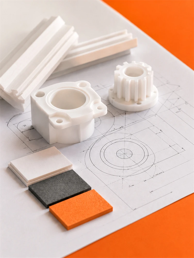
Engineering plastic parts suit friction, guide, support, buffer, anti-corrosion and insulation areas. We supply UHMWPE, POM, PA, PP/PE components for conveyor, food, mining, machinery, chemical and cable systems, with custom OEM service available.
Stay updated with our latest industry insights, company updates and featured articles.
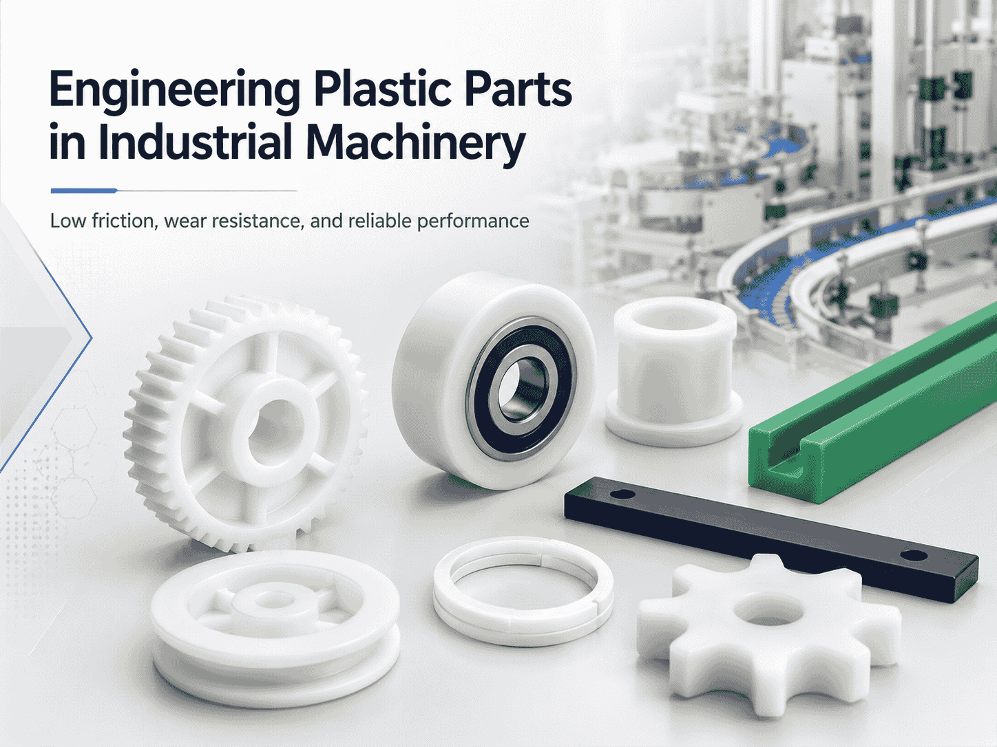
Engineering plastics are increasingly used in industrial machinery, automated production lines, conveyor systems, packaging equipment, and food-processing machines. Materials such as nylon, UHMWPE, POM, and
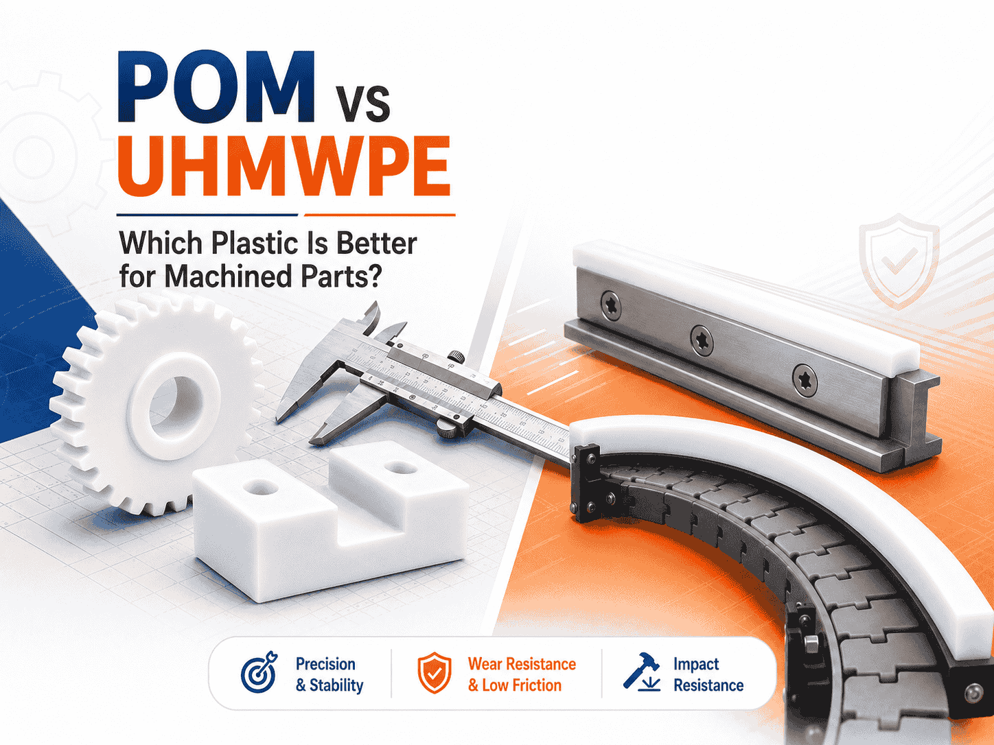
Both are lightweight, corrosion-resistant, wear-resistant, and suitable for CNC machining. However, they perform very differently
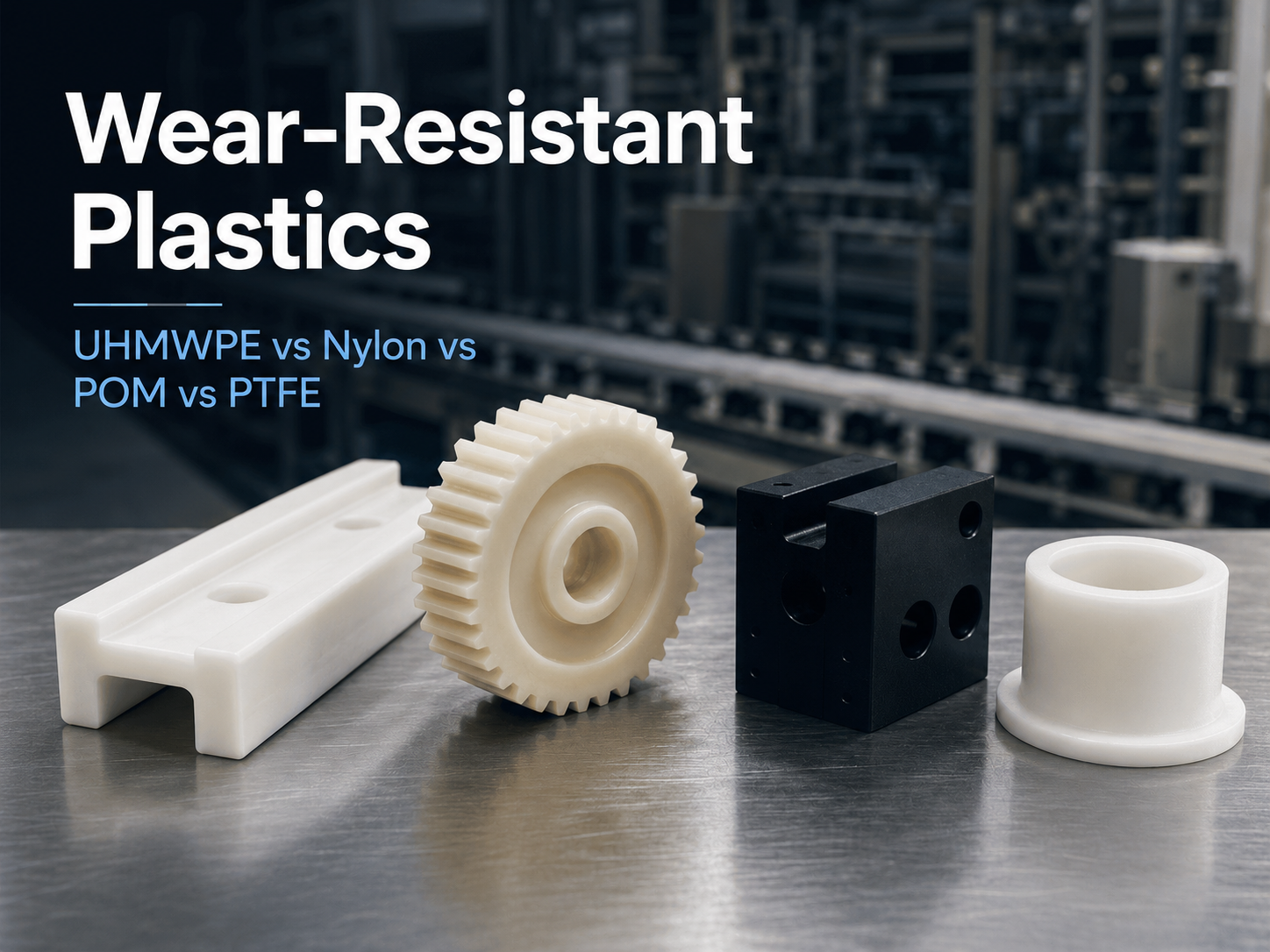
Wear is a common cause of failure in conveyor systems, packaging machinery, automated equipment, mining
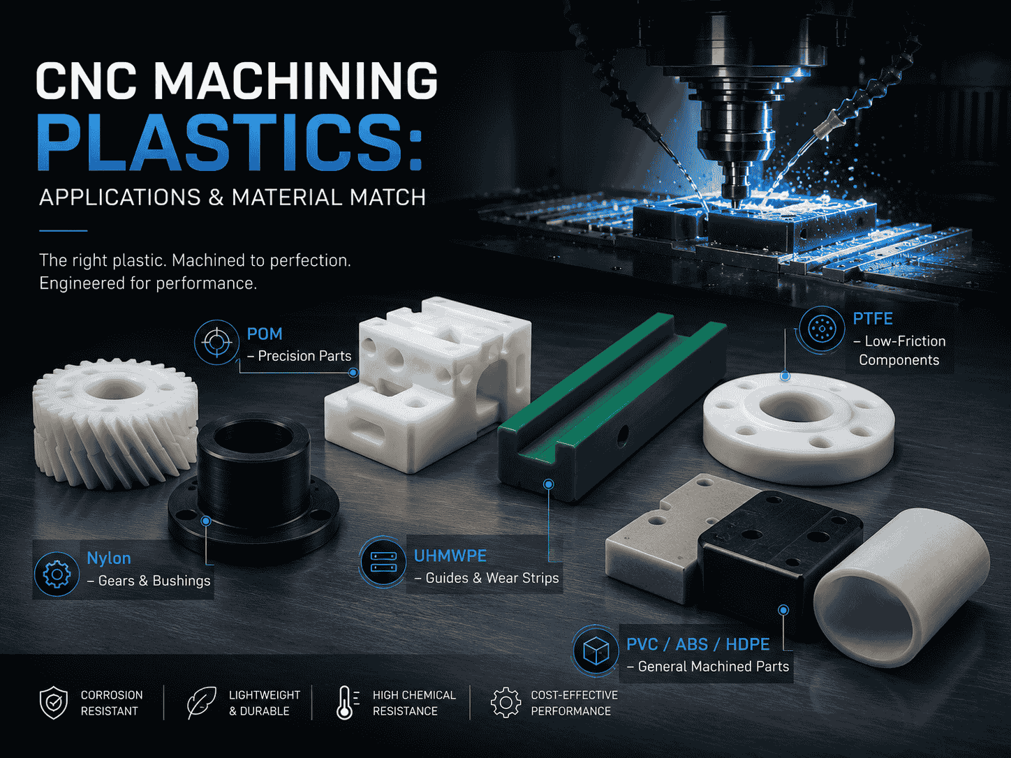
CNC machining is widely used to produce plastic prototypes, low-volume parts, replacement components, jigs, fixtures,
Both are lightweight, corrosion-resistant, wear-resistant, and suitable for CNC machining. However, they perform very differently
Wear is a common cause of failure in conveyor systems, packaging machinery, automated equipment, mining
CNC machining is widely used to produce plastic prototypes, low-volume parts, replacement components, jigs, fixtures,
Need UHMWPE sheets & custom plastic machined/OEM parts?Send specs & material needs, free quote within 24h.