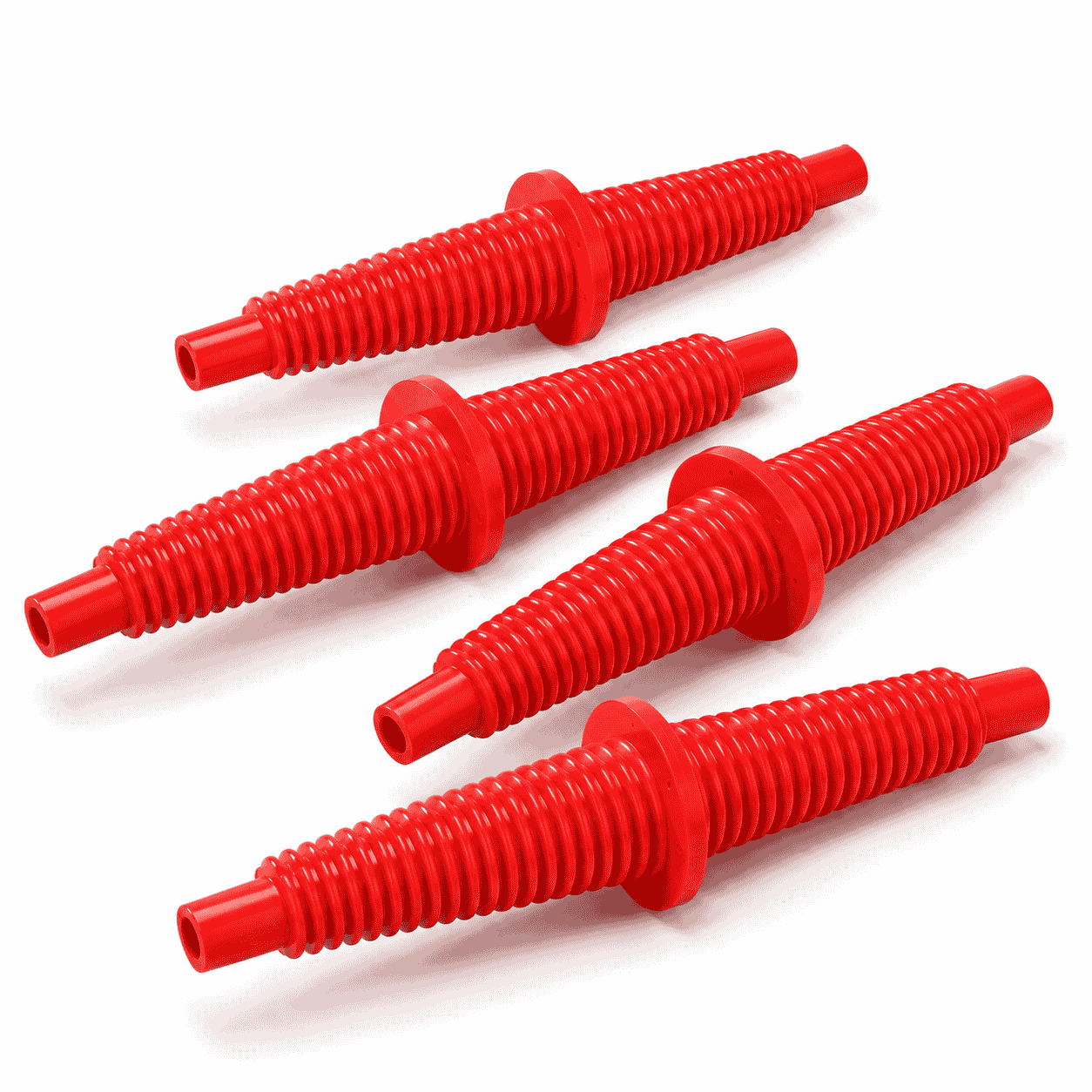
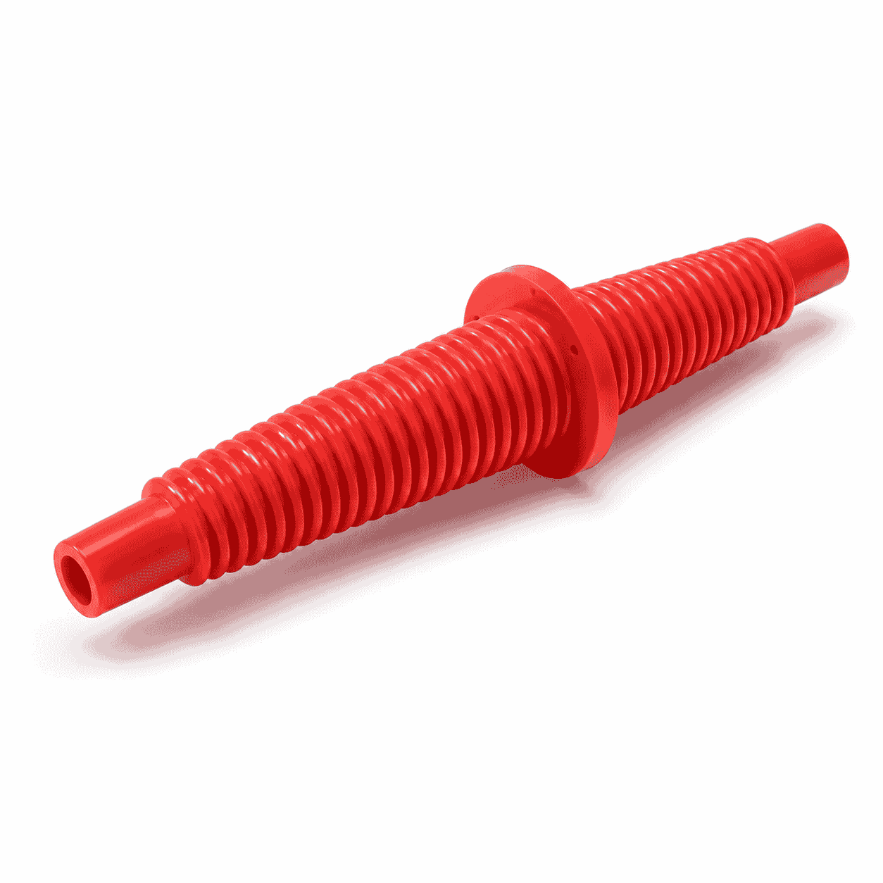
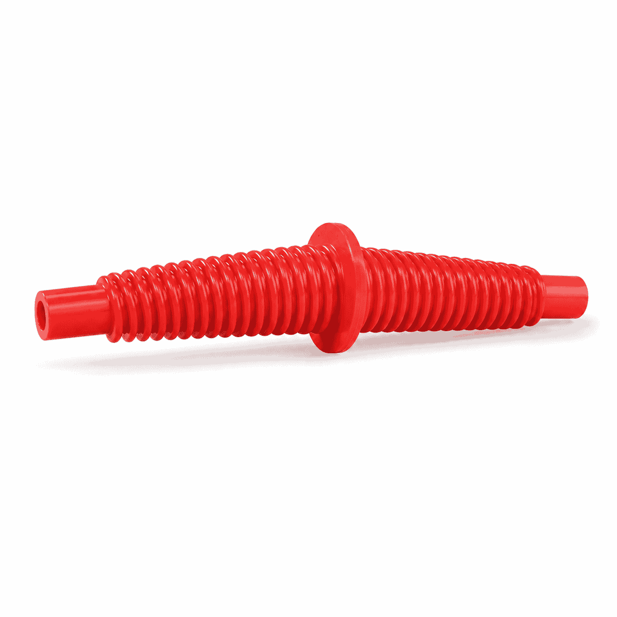
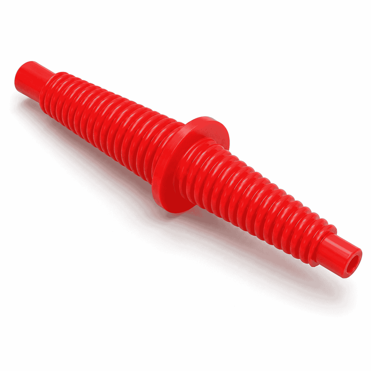
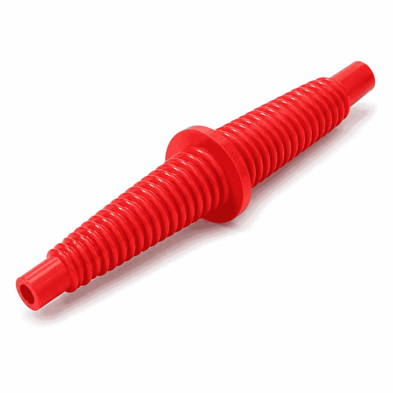
CNC Machined UHMWPE Auger Screw is a custom engineering plastic component featuring continuous helical working surfaces, a central locating flange, shaft ends and axial mounting holes.
It can be used for material conveying, feeding, separation, positioning and controlled product movement. Screw pitch, spiral direction, diameter, flange, shaft holes and material grade can be manufactured according to drawings or physical samples.
CNC Machined UHMWPE Auger Screw is a custom engineering plastic component featuring continuous helical working surfaces, a central locating flange, cylindrical shaft ends and axial mounting holes. Depending on the equipment design, it can be used for material conveying, feeding, separation, pushing, positioning, turning or controlled product movement.
The products shown are manufactured in a long double-ended structure. Each side contains a continuous spiral profile, while the enlarged flange in the middle may provide installation positioning, axial limitation, connection or separation between two working sections.
The exact function of the CNC Machined UHMWPE Auger Screw cannot be confirmed from appearance alone. Its operating purpose, rotation direction, pitch, material grade and installation method should be determined according to the complete equipment assembly, technical drawing and actual working conditions.
The photographed parts have a relatively complex one-piece structure rather than a simple cylindrical plastic rod. Visible features include:
The spiral may be manufactured with constant pitch, variable pitch, single-start, multi-start, left-hand or right-hand configurations. These details must be confirmed before machining because they directly affect the movement direction and delivery rate of the material.
When the screw rotates inside a matching trough, sleeve or guide structure, its helical profile can move granular, powdered, block-shaped or packaged materials along the axial direction.
A conventional screw conveyor uses a rotating helical element to move material. However, the photographed product should only be described as a conveyor screw after its installation position has been confirmed.
The spiral profile can feed material into the next processing station at a controlled rate. The pitch, rotational speed and working diameter influence the amount and speed of material movement.
In selected equipment, the spiral can create spacing between products or separate continuously arriving components. Variable-pitch structures may gradually increase or reduce product spacing.
The spiral groove or flight can guide products into a specified position before filling, packaging, inspection, cutting or assembly.
The rotating screw can push material toward an outlet, discharge opening or transfer position. It may also help prevent material from accumulating in one section of the equipment.
Depending on the shape of the spiral working surface, the component may turn, redistribute or agitate products during rotation.
When designed with suitable clearance, the screw profile may help move residual material away from the inner wall of a trough or sleeve. It should not be described as completely self-cleaning unless verified by the equipment manufacturer.
UHMWPE is an abbreviation for ultra-high-molecular-weight polyethylene. It is a polyethylene engineering plastic known for low friction, abrasion resistance, impact resistance and very low moisture absorption.
General material information is available from Wikipedia’s explanation of ultra-high-molecular-weight polyethylene.
Material sheets for machining are available from our Ultra High Molecular Weight Polyethylene UHMWPE Sheet category.
The relatively low-friction surface helps materials slide along the screw profile and can reduce resistance between the screw and the corresponding guide, sleeve or trough.
The helical surface repeatedly contacts the conveyed material and surrounding equipment. Properly selected UHMWPE can provide good wear performance in many moderate-load conveying and guiding applications.
UHMWPE can absorb impact generated when irregular products, particles or mechanical components contact the spiral working surface.
UHMWPE absorbs very little moisture compared with materials such as nylon. This characteristic is useful for components operating in humid, wet or frequently cleaned environments.
UHMWPE does not rust like carbon steel and is resistant to many acids, alkalis and ordinary industrial chemicals. Chemical compatibility should still be checked for strong oxidizing substances and special solvents.
Replacing selected metal contact parts with UHMWPE can reduce hard collision, vibration transmission and operating noise.
UHMWPE is much lighter than steel. Large or long screw components are therefore easier to handle, install and replace.
The plastic working surface is less likely to scratch many containers, coated parts and finished products than an unfinished or damaged metal spiral.
Traditional metal screws can experience corrosion, high noise, heavy weight, material scratching and product adhesion. A properly designed CNC Machined UHMWPE Auger Screw may help address the following problems:
The actual improvement depends on the material type, rotational speed, load, installation clearance and equipment structure.
CNC Machined UHMWPE Auger Screw components may be used in different types of conveyor systems and industrial material-handling equipment.
Possible applications include:
Additional application information is available from our Mining and Bulk Material Handling page.
These are possible application categories based on the visible spiral structure. The photographed product should not be assigned to a specific industry without confirming the equipment drawing and installation position.
Each CNC Machined UHMWPE Auger Screw can be manufactured according to the required movement path, installation structure and working conditions.
Available custom options include:
A constant-pitch structure maintains a similar axial distance between adjacent spiral sections. It can be used where relatively uniform material movement is required.
A variable-pitch structure gradually changes the distance between adjacent spiral sections. Depending on its design, it may increase product spacing, reduce spacing, accelerate movement or create controlled compression.
Variable-pitch screws require accurate confirmation of the starting pitch, ending pitch, transition position and direction of rotation.
The irregular helical profile can be manufactured through computer numerical control machining.
Our CNC Plastic Machining service supports screw components manufactured from drawings or physical samples.
Possible manufacturing operations include:
CNC Machined UHMWPE Auger Screw components contain long helical surfaces, thin flight edges and uneven material distribution. These features may create several machining challenges.
The machining sequence, cutting parameters, fixture method and inspection reference should be selected according to the screw length, diameter, pitch and wall thickness.
To manufacture the CNC Machined UHMWPE Auger Screw correctly, the following information should be provided or confirmed:
When the original drawing is unavailable, an existing UHMWPE auger screw can be measured and reproduced. However, wear, deformation and damaged flight edges on the old component should not be copied directly.
The following areas should be checked before reverse engineering:
Providing the corresponding sleeve, trough, shaft or equipment dimensions can improve the accuracy of the replacement component.
Important inspection items for a CNC Machined UHMWPE Auger Screw include:
For rotating components, concentricity and weight distribution should be checked to reduce abnormal vibration during operation.
UHMWPE offers good wear, impact and sliding performance, but it has lower rigidity than many metals and some engineering plastics. Long components or heavily loaded shafts may require a metal core, larger wall thickness or additional support.
UHMWPE can also deform gradually under continuous load. Shaft connection, bearing support, operating temperature and long-term pressure should therefore be considered during structural design.
Applications involving high rotational speed, high temperature, high torque or very tight dimensional tolerances require a separate engineering evaluation before production.
The red appearance of the photographed CNC Machined UHMWPE Auger Screw does not prove that it is food grade. Food-contact suitability depends on the exact resin grade, additives, colorants, production records and compliance documents.
For food, beverage or pharmaceutical machinery, the following should be confirmed:
CNC Machined UHMWPE Auger Screw is a custom helical engineering plastic component that can be used for conveying, feeding, positioning, separation, pushing and controlled material movement.
Its pitch, spiral direction, outside diameter, shaft structure, central flange, mounting holes and material grade can be manufactured according to drawings, physical samples and actual equipment conditions.
Proper material selection and machining control can help reduce friction, corrosion, product scratching, operating noise and component weight while providing a replaceable working component for industrial equipment.
Check drawings for full specifications and confirm materials according to service conditions to prevent product defects.
Inspect all key processing steps and fully verify dimensions, holes, grooves and fitting surfaces.
Deburr, chamfer and clean products for easy installation. Ensure uniform quality among batch products.
Choose appropriate packaging solutions based on product features to protect goods from collision, deformation and mixing during transit.
Unlike metal parts, engineering plastic components still require strict control over dimensions, holes, edges, surface, materials and assembly performance for equipment use.
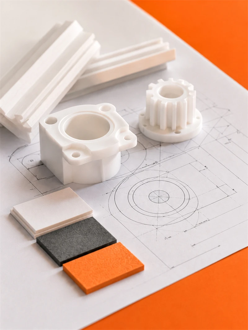
Engineering plastic parts suit friction, guide, support, buffer, anti-corrosion and insulation areas. We supply UHMWPE, POM, PA, PP/PE components for conveyor, food, mining, machinery, chemical and cable systems, with custom OEM service available.
Stay updated with our latest industry insights, company updates and featured articles.
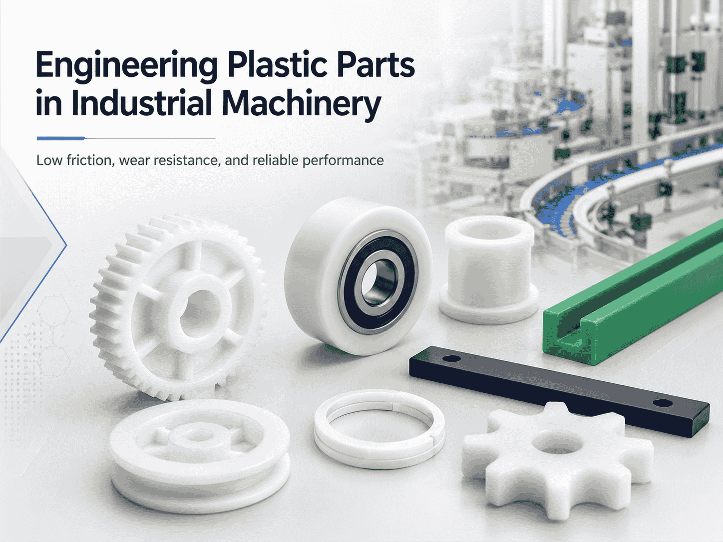
Engineering plastics are increasingly used in industrial machinery, automated production lines, conveyor systems, packaging equipment, and food-processing machines. Materials such as nylon, UHMWPE, POM, and
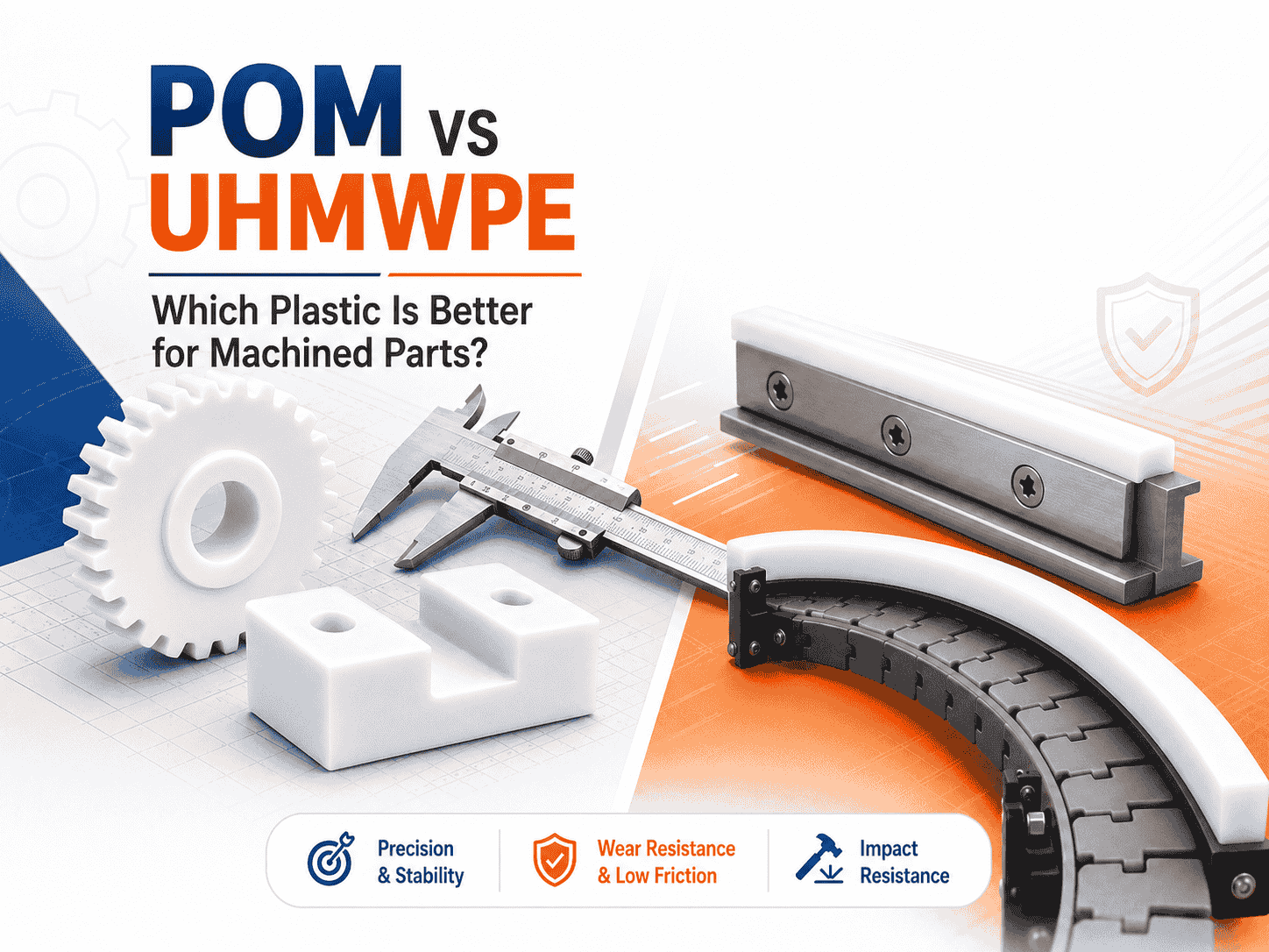
Both are lightweight, corrosion-resistant, wear-resistant, and suitable for CNC machining. However, they perform very differently
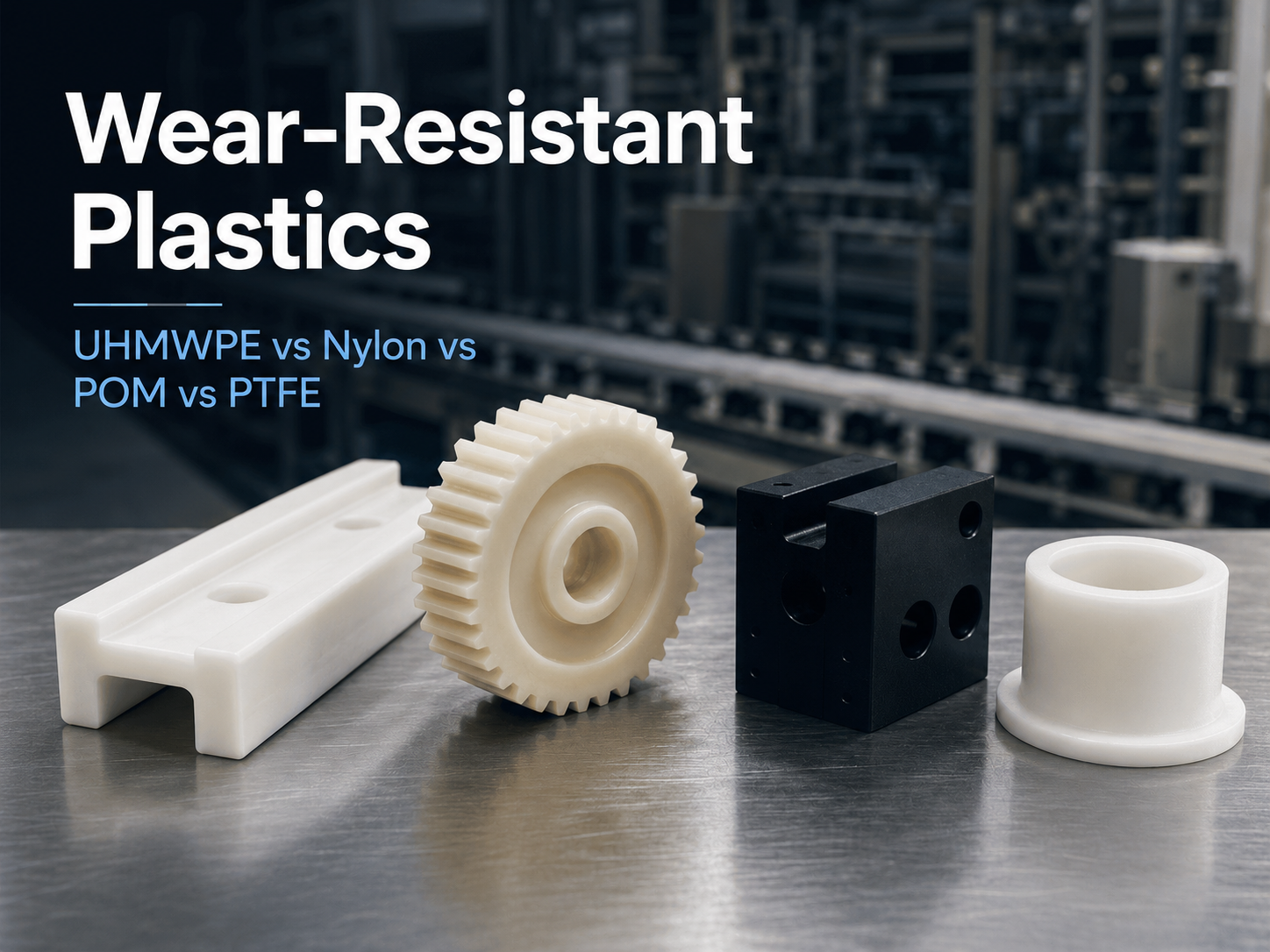
Wear is a common cause of failure in conveyor systems, packaging machinery, automated equipment, mining
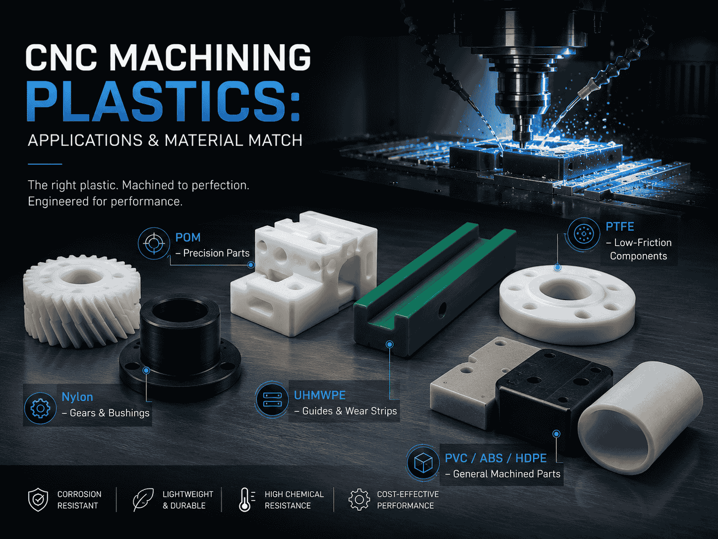
CNC machining is widely used to produce plastic prototypes, low-volume parts, replacement components, jigs, fixtures,
Both are lightweight, corrosion-resistant, wear-resistant, and suitable for CNC machining. However, they perform very differently
Wear is a common cause of failure in conveyor systems, packaging machinery, automated equipment, mining
CNC machining is widely used to produce plastic prototypes, low-volume parts, replacement components, jigs, fixtures,

Need UHMWPE sheets & custom plastic machined/OEM parts?Send specs & material needs, free quote within 24h.