

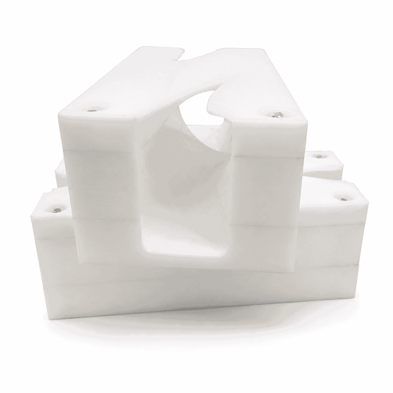
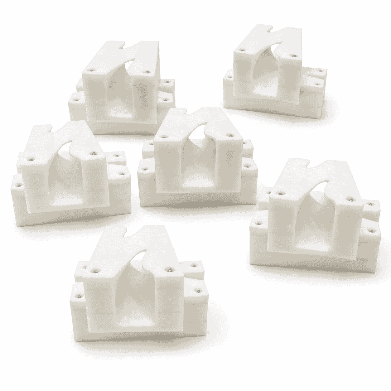
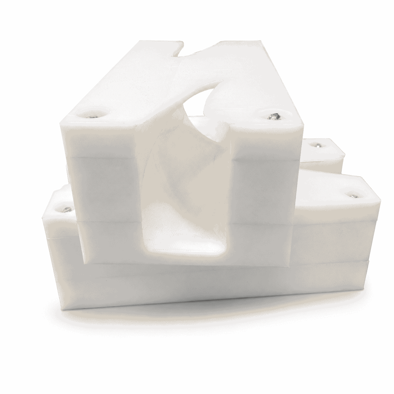
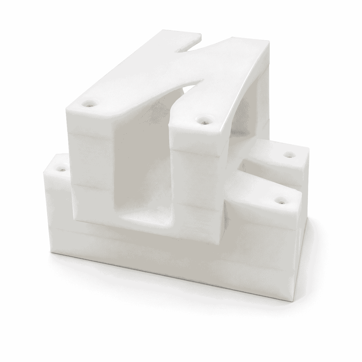
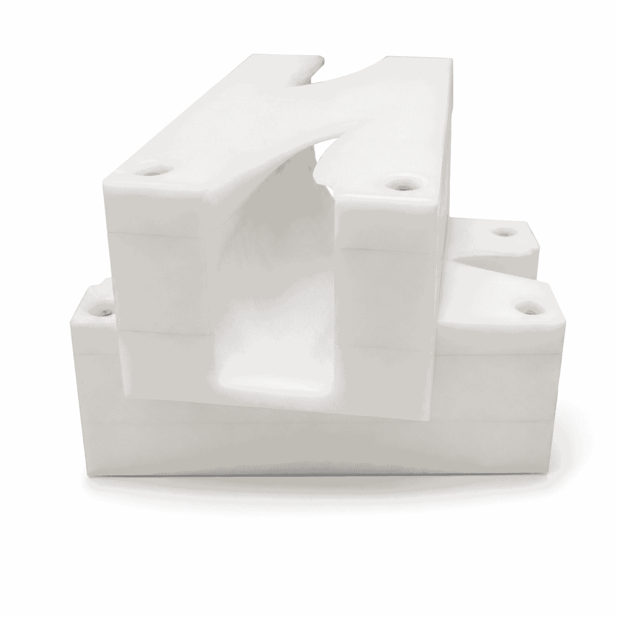
CNC Machined Can Inverter Block is a custom engineering plastic guide component used to change the orientation of cans and suitable containers during continuous conveyor operation.
The internal curved or twisted channel can be manufactured for custom container sizes, turnover angles and rotation directions. UHMWPE, POM, nylon and other engineering plastics are available according to the operating conditions.
CNC Machined Can Inverter Block is a custom engineering plastic guide component used to change the orientation of cans and other suitable containers while they move along a conveyor line. Its internal curved or twisted guide channel gradually controls the container path, allowing the can to turn smoothly without requiring a separate powered rotating mechanism.
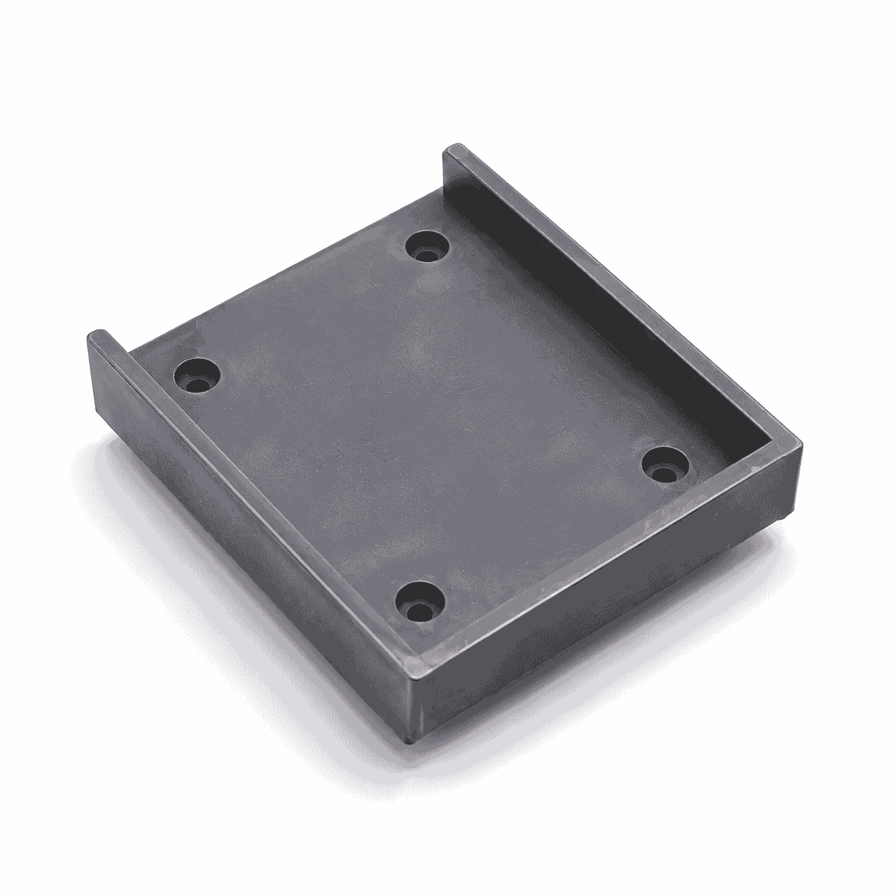
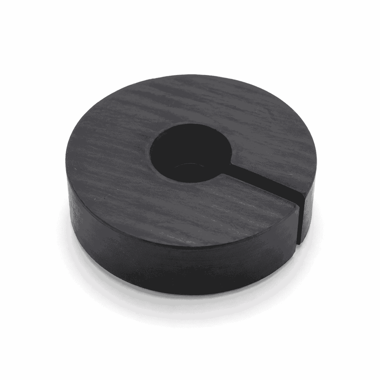
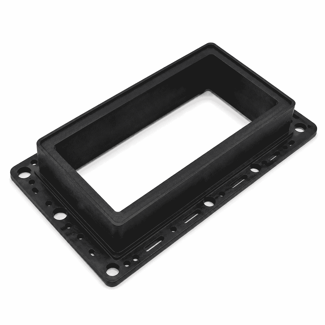
The photographed component features a thick rectangular body, a specially machined internal guide channel and several mounting holes. Multiple sections can be installed together to form a continuous turnover path. The channel dimensions, turnover direction, installation holes and overall structure are manufactured according to the container size and conveyor layout.
A CNC Machined Can Inverter Block is commonly used where cans must be inverted before or after washing, heat treatment, drying, coding, inspection or other packaging processes. The actual turnover angle, installation position and working direction must be confirmed from the equipment drawing and production-line requirements.
The can inverter block is different from a conventional flat guide plate. Its main functional feature is the three-dimensional internal guide path. As a can enters the channel, the surrounding surfaces gradually change its orientation until it reaches the required outlet position.
Typical structural features include:
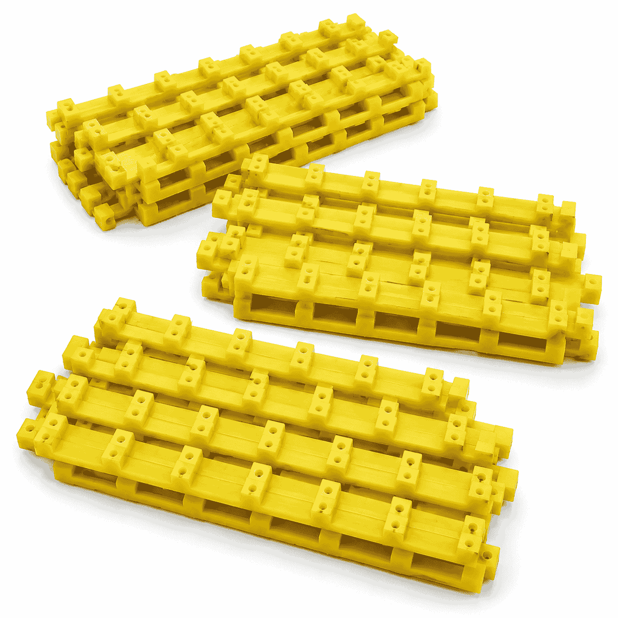
The photographed parts appear to use several stacked or connected sections. This type of modular structure makes complex internal paths easier to manufacture, inspect, install and replace.
The main function of the CNC Machined Can Inverter Block is to change the orientation of a moving container. A typical design turns the container through 180 degrees, although 90-degree or other custom orientation changes may also be produced.
The container normally continues moving through the guide channel under conveyor force. This allows the turnover process to be integrated into the production line without stopping each can for separate handling.
The internal profile maintains the can within the intended path during rotation. Correct clearance helps reduce uncontrolled shaking, lateral movement and misalignment.
The inverter can place the top, bottom or side of the container in the required position before inspection, cleaning, printing, drying or another production process.
The guide block can be installed between two conveyor sections or processing stations, allowing the container to enter the next machine in the required orientation.
The engineering plastic block acts as a replaceable container-contact component. When the guide surface becomes worn, the block can be replaced without rebuilding the complete conveyor frame.
The operation of a CNC Machined Can Inverter Block can generally be divided into four stages:
The inlet, transition and outlet profiles must connect smoothly. Sudden changes in the channel may cause impact, scratching, jamming or unstable discharge.
CNC Machined Can Inverter Block components can be integrated into different types of conveyor systems and packaging machinery.
Typical applications may include:
General information about material transport equipment is available from Wikipedia’s explanation of a conveyor system.
The exact use of the photographed product cannot be confirmed without the complete conveyor assembly. It should therefore be described as a custom can inverter or container turnover guide rather than assigning it to one specific machine model.
The material should be selected according to conveyor speed, container material, impact, surface requirements, temperature, humidity, cleaning method and dimensional tolerance.
UHMWPE Sheet is commonly considered for guide blocks requiring low friction, impact resistance, wear resistance and low moisture absorption.
Wikipedia provides a basic explanation of ultra-high-molecular-weight polyethylene.
Typical characteristics include:
UHMWPE has lower rigidity than POM and many nylon grades. Thick wall sections and adequate mounting support may therefore be required for large can inverter blocks.
POM can be considered where higher rigidity, improved dimensional stability and tighter machining tolerances are required. It is suitable for smaller guide components or accurately fitted structures.
However, POM is generally less impact-tolerant than UHMWPE in severe collision conditions. Cleaning chemicals and operating temperature must also be reviewed.
Nylon may be selected where the guide block requires greater mechanical strength, toughness and load-bearing capacity. It can be machined into thick and complex three-dimensional structures.
Nylon absorbs more moisture than UHMWPE and POM. Moisture-related dimensional changes should therefore be considered when the internal guide clearance is relatively small.
A metal can turnover guide can be heavy, noisy and more likely to mark the surface of a container. Properly selected engineering plastic provides a smoother and replaceable guide surface.
An incorrectly designed or worn turnover guide may cause cans to jam, collide, fall or leave the guide in the wrong orientation. A correctly manufactured CNC Machined Can Inverter Block can help address the following problems:
The actual operating result depends on the guide profile, conveyor speed, container dimensions, surface condition and installation accuracy.
CNC Machined Can Inverter Block components can be produced for different container structures, provided that the container shape and mechanical strength are suitable for guided turnover.
Possible container types include:
Glass bottles and thin-wall containers require additional evaluation because incorrect clearance or excessive impact may cause breakage, deformation or surface damage.
The internal channel can be designed according to the required orientation change.
The turning direction must be clearly marked on the drawing because left-hand and right-hand parts are not normally interchangeable.
Available machining operations include:
The basic principles of programmed machine-tool processing are explained in Wikipedia’s article about computer numerical control.
A CNC Machined Can Inverter Block may contain a deep three-dimensional curved passage. Compared with a flat guide plate, several machining details require additional attention:
If the guide is divided into several parts, each joint surface must be machined accurately. An offset between two adjacent sections may interfere with the can or create an impact point.
To manufacture the CNC Machined Can Inverter Block correctly, the following information should be provided or confirmed:
When the original drawing is unavailable, an existing can inverter block can be measured and reproduced. However, wear, impact damage and deformation on the used component should not be copied directly.
Reverse engineering should include checks of:
Providing the actual can or container together with the worn guide block can improve profile verification and clearance control.
Important inspection items for a CNC Machined Can Inverter Block include:
Where possible, the finished guide can be checked with a matching container or inspection model before delivery.
The white appearance of the photographed component does not prove that the CNC Machined Can Inverter Block is food-contact compliant. Suitability depends on the exact resin grade, additives, colorants, production records and required test documents.
For food and beverage canning equipment, the following should be confirmed:
CNC Machined Can Inverter Block is a custom engineering plastic guide component used to change the orientation of cans and suitable containers during continuous conveyor operation.
Its internal guide channel, turnover angle, rotation direction, mounting structure and container clearance can be manufactured according to drawings, physical samples and actual production-line requirements.
UHMWPE, POM, nylon and other engineering plastics can be selected according to friction, impact, dimensional stability, temperature, cleaning conditions and compliance requirements.
Check drawings for full specifications and confirm materials according to service conditions to prevent product defects.
Inspect all key processing steps and fully verify dimensions, holes, grooves and fitting surfaces.
Deburr, chamfer and clean products for easy installation. Ensure uniform quality among batch products.
Choose appropriate packaging solutions based on product features to protect goods from collision, deformation and mixing during transit.
Unlike metal parts, engineering plastic components still require strict control over dimensions, holes, edges, surface, materials and assembly performance for equipment use.
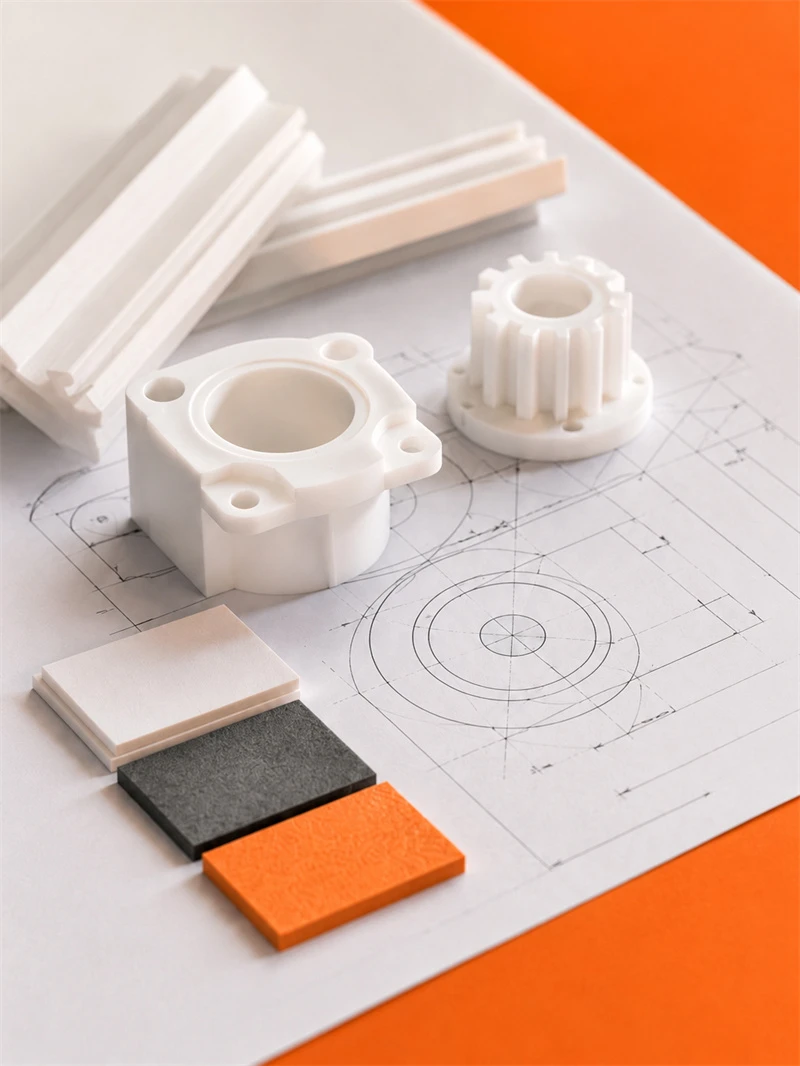
Engineering plastic parts suit friction, guide, support, buffer, anti-corrosion and insulation areas. We supply UHMWPE, POM, PA, PP/PE components for conveyor, food, mining, machinery, chemical and cable systems, with custom OEM service available.
Stay updated with our latest industry insights, company updates and featured articles.
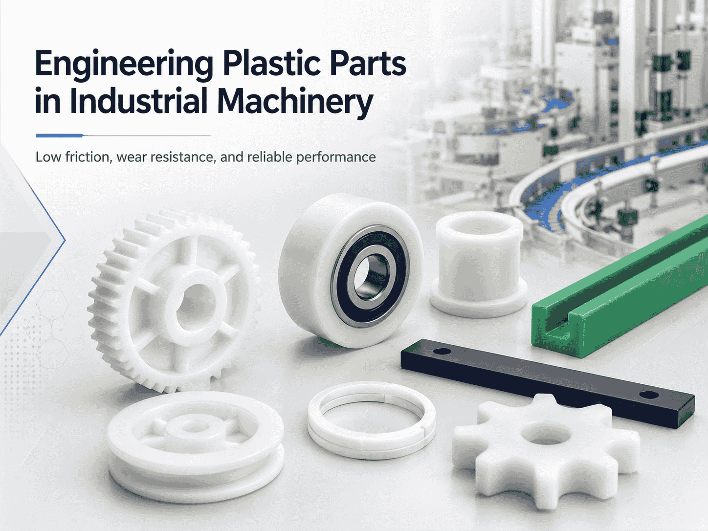
Engineering plastics are increasingly used in industrial machinery, automated production lines, conveyor systems, packaging equipment, and food-processing machines. Materials such as nylon, UHMWPE, POM, and
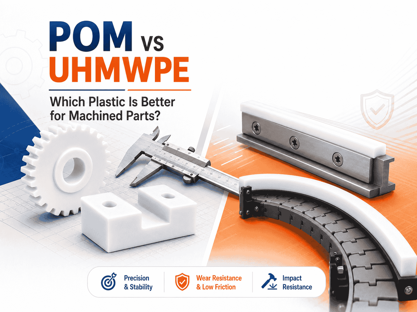
Both are lightweight, corrosion-resistant, wear-resistant, and suitable for CNC machining. However, they perform very differently
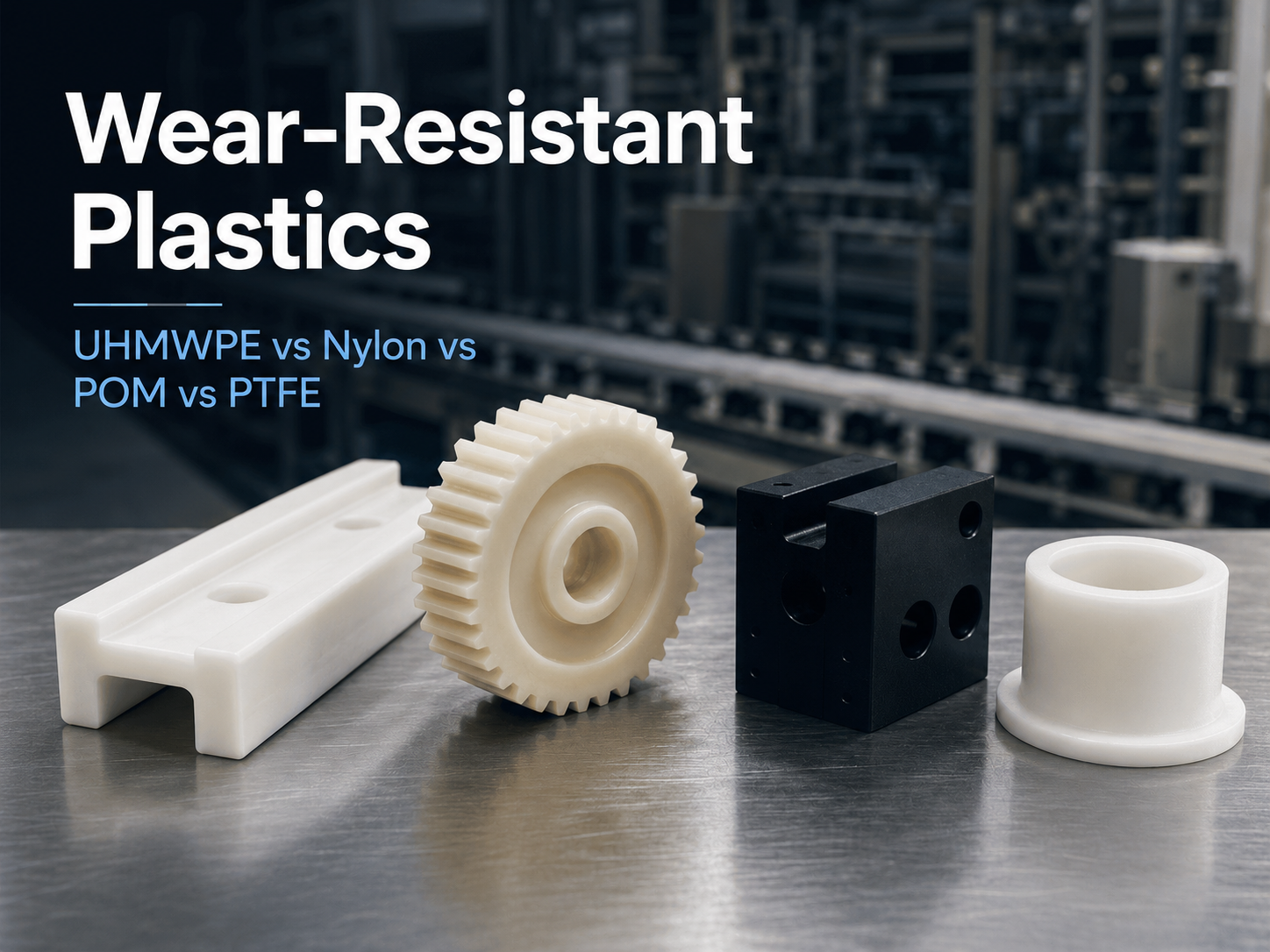
Wear is a common cause of failure in conveyor systems, packaging machinery, automated equipment, mining
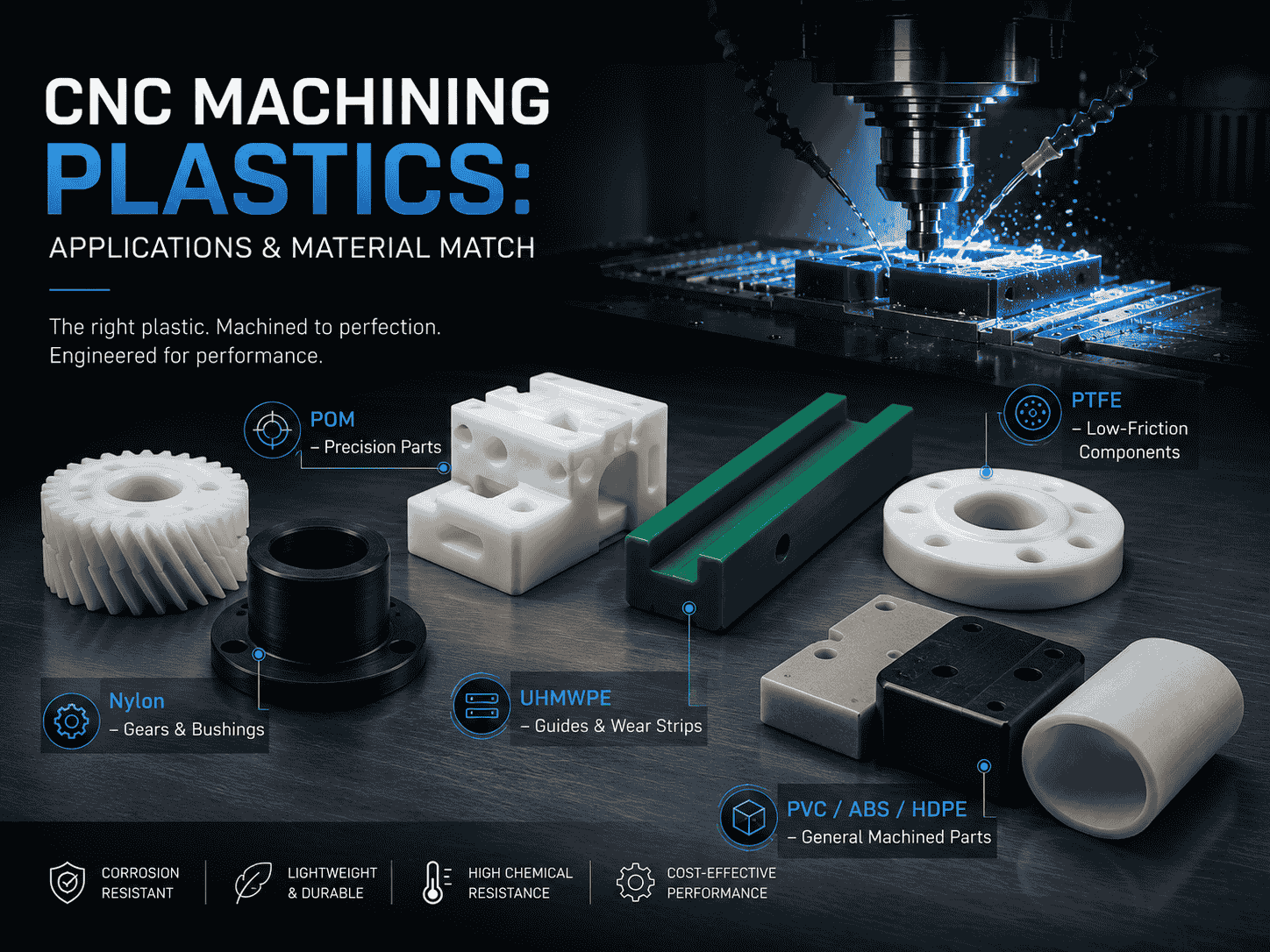
CNC machining is widely used to produce plastic prototypes, low-volume parts, replacement components, jigs, fixtures,
Both are lightweight, corrosion-resistant, wear-resistant, and suitable for CNC machining. However, they perform very differently
Wear is a common cause of failure in conveyor systems, packaging machinery, automated equipment, mining
CNC machining is widely used to produce plastic prototypes, low-volume parts, replacement components, jigs, fixtures,
Need UHMWPE sheets & custom plastic machined/OEM parts?Send specs & material needs, free quote within 24h.